Technological advances have driven down prices while increasing functionality.
In network cabling systems, media converters sometimes are viewed as temporary, stopgap, or work-around solutions for users who want fiber in the horizontal or require link distances that copper will not support. While some of these perceptions may be based on the physical appearance of media converters within cabling systems, the perceptions are not accurate. Media conversions are integrated parts of structured cabling systems, and they are within the scope of current technology and application standards.
This article will provide perspective on standards efforts that have helped, and hindered, fiber-to-the-desk deployment; it will also detail technological developments that are making media converters less-visible and more-integrated parts of fiber systems.
Standards hurdles
The 802.3 body of the Institute of Electrical and Electronics Engineers (IEEE-www.ieee.org) established early standards for 10- and 100-Mbit/sec Ethernet applications, including the 10Base-FL and 100Base-FX (fiber) and 10Base-T and 100Base-TX (copper) specifications. The media, distance, and connector interfaces defined within the 10Base-T and 100Base-TX copper-based standards are the same. More importantly, from an IEEE perspective, a defined standard-ANSI/TIA/EIA-568B.3-is in place for unshielded twisted-pair (UTP) cabling. And Category 5 cable can be used for 10Base-T or 100Base-TX.
Additionally, most installers and users are more familiar with UTP than with fiber. And most Ethernet ports-such as network interface cards (NICs) and PC motherboards-support both 10Base-T and 100Base-TX. All these factors make UTP an easy and popular choice among cabling system installers and users. In contrast, standard specifications governing optical-based transmission traditionally have put obstacles in the paths of users considering deploying fiber in the horizontal.
One fact that has significantly slowed deployment of horizontal fiber is that the 10 and 100 Mbit/sec optical Ethernet standards specify different source wavelengths and coupler interfaces. The 10Base-FL standard specifies an 850-nanometer (nm; short-wavelength) LED source and ST connector interface; the 100Base-FX standard specifies a 1300-nm (long-wavelength) LED source and duplex SC connector interface. That means users upgrading from 10Base-FL to 100Base-SX must physically change the optical source and receiver, as well as the NICs at the workstations and within hubs and switches (because of the dissimilar ST and SC interfaces).
Why did the IEEE do this? The answer is in the performance of fiber cable. When the IEEE standards were set, 62.5/125-µm multimode fiber cable had a bandwidth at 850 nm of 160 MHz·km. The desired distance for 10Base-FL is 2 km. Therefore, the fiber's bandwidth is reduced to 80 MHz at 2 km. This bandwidth level is sufficient for 10 Mbit/sec Ethernet, but not for 100 Mbit/sec Ethernet. At 1300 nm, the bandwidth of multimode fiber is 400 MHz·km; at a distance of 2 km, the effective bandwidth is 200 MHz, which is sufficient for both 10 and 100 Mbit/sec applications.
By using different wavelengths and interfaces for 10 Base-FL and 100Base-FX, the IEEE ensured there could never be an optical link established between the two. But it also ensured a difficult and costly upgrade path from 10 to 100 Mbits/sec.
A simple solution is to use 1300-nm optics for both 10 and 100 Mbit/sec Ethernet. But these long-wavelength optics are more costly and less flexible than the short-wavelength 850-nm variety. Even though the cost of 1300-nm devices has dropped considerably over the past 18 to 24 months, they are still up to 250% the cost of 850-nm devices.
100Base-SX gets things going
The establishment of the 100Base-SX standard by the TIA-formally titled the TIA/EIA-785 100 Mbit/sec Physical Layer Dependent Sub-layer and 10 Mbit/sec and 100 Mbit/sec Auto-Negotiation on 850-nm Short Wavelength-opened new opportunities for users to deploy horizontal fiber. The "Short-Wavelength Fast Ethernet" specifications, as they have been called, allow users to migrate from 10 to 100 Mbits/sec over multimode fiber using 850-nm optics.
The standard supports a multimode cable distance of 300 meters-an optimum length for horizontal applications. It was based on a model that used worst-case values and assumptions, such as the use of 62.5-µm fiber with 160 MHz·km bandwidth. In reality, most 100Base-SX equipment will support a distance of 500 meters if good quality multimode fiber is in the link.
Where media converters fit in
Media converters can be a crucial part of the implementation of TIA/EIA-785 and, therefore, a key component in a user's migration path to higher speeds over multimode fiber. Advances in media conversion technology, coupled with the recent release of the 785 standard, make it more realistic than ever for users to do exactly that.
Most media converters are designed to be application-specific, meaning the converter will support only one or at most two similar applications. For example, a media converter may support 10 Mbit/sec Ethernet (converting 10Base-T to 10Base-FL), 100 Mbit/sec Ethernet (100Base-TX to 100Base-FX), or 10/100 Mbit/sec Ethernet (100Base-SX, dual protocol 10/100 Mbit-sec Ethernet).
The primary reason that media converters are application-specific is the technical complexity required for each application-and the associated cost to handle multiple applications in one media-converter unit. Considering the significant differences in copper and fiber application protocols, and in optical transmitter and detectors, multiple applications can escalate the cost of a media converter.
Take, as an example, the user who must set up a 10 Mbit/sec Ethernet link to a microcontroller on a factory floor. The nearest telecommunications room is 450 meters away. The microcontroller has a built-in Ethernet port and spare Ethernet switch ports available in the TR. The solution: Use multimode fiber and a media converter on each end of the link. The choice of media converters comes down to economics: pay $140 for two 10-Mbit/sec converters, or pay $1,800 for a do-it-all converter that supports 10, 100, and 1000 Mbit/sec Ethernet over either multimode or singlemode fiber.
Single-application media converters mean a simpler product design, reduced development overhead, quicker time to market, and easier field deployment. In short, single-application drives costs down.
Practical application layouts
Media converters can fit into any number of places within a network. Whether at the workstation, in the TR, or even in between, converter placement must be carefully considered and followed out to achieve maximum efficiency. Here's where and how media conversion typically is used:
- Point-to-point links. LAN media converters are designed to support point-to-point links. The two basic configurations in which media converters are used in LAN applications are workstation to hub/switch and hub/switch to hub/switch.
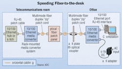
In the first configuration, the workstation and switch are equipped with the standard 8-pin modular UTP interface. Media converters are used to connect the devices at each end to the fiber cable. This is the generic fiber-to-the-desk application, where hub equipment is located in a remote or centralized TR.
In the second configuration, the media converters are used to interconnect two UTP-based hubs/switches via a fiber link. This is a typical campus configuration, where the hubs or switches may be located in separate TRs or even in separate buildings. In the latter application, the fiber link provides surge and lightning protection.
- Workstations to hubs/switches. Media converters can be used to link a workstation equipped with an 8-pin modular port to an all-optical switch or hub. The optical support from the hub or switch must be considered before selecting the media converter. The majority of all optical hubs operate at 850 nm and support only 10 Mbit/sec Ethernet, while the majority of optical switches operate at 1300 nm and support 100 Mbit/sec Ethernet only.
- Conversion in the TR. The hub or switch end of an optical link using media converters is normally located in a TR. A telecom-style media converter should be a chassis-based, rack-mountable unit that operates with either AC or DC power. It should provide hot-swap redundancy and support a high number of ports. Separation of copper and fiber media is an important feature, to help prevent damage to optical-fiber cables. And the converter should be scalable, to allow the system to grow on an incremental or as-needed basis.
- Conversion at workstations. The typical media converter arrangement at the workstation includes the media converter, a power module, an optical patch cord, a UTP patch cord, a work area faceplate, and some form of optical coupler in the faceplate. The media converter sits either on the floor or in a holder attached to the faceplate. The exposed optical patch cord connects the media converter to the coupler in the faceplate. The media converter itself requires an external power brick that plugs into an AC outlet.
In general, these workstation media converters are not robust or reliable solutions. Overall, the solution is fragile, with the media-conversion circuitry and a fiber jumper left exposed. Also, these solutions are expensive to maintain, especially considering replacement costs for damaged fiber jumpers and media converters. Some users have reported spending tens of thousands of dollars annually to replace fiber jumpers damaged in the office environment.
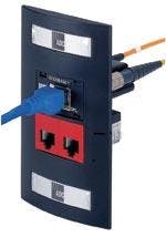
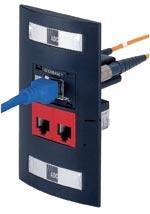
Advances in chip technology and packaging techniques have made workstation media conversion less fragile and more cost-effective. For example, users can now choose a line of 10/100 Mbit/sec Ethernet media converters that mount behind the work area faceplate, with all the conversion circuitry securely behind the faceplate. This converter design obtains power from the PC through the PS/2 mouse port or USB port. Most importantly, there is no need for an optical patch cord between the PC and the converter- just a standard 8-pin modular patch cable connecting the faceplate to the PC. The elimination of the optical patch cord and the external power brick rids the user of the costs and downtime associated with typical media converter solutions. Finally, the wall-mount media converter provides auto-negotiation over both the UTP and fiber segments, per the requirements of TIA/EIA-785.
- Conversion with the MUTOA. TIA's TSB-75 is a set of specifications that covers zone distribution, and maintains the TIA limit of 90 meters for UTP from the TR to the work area. This 90-meter limit gave rise to the need for the multi-user telecommunications outlet assembly (MUTOA). A MUTOA is a point at which horizontal cables are terminated into modular connectors for interconnection with the work area equipment, including phones, PCs, and network printers. The key to the MUTOA concept is that the horizontal cabling between the TR and the MUTOA is fixed; it never changes. All changes are made using patch cables between the user equipment and the modular ports within the MUTOA.
In a copper MUTOA, the combined distance of the patch cords and the horizontal cable between the work area and the TR is limited to the usual 100 meters. The tradeoff between the patch cord and horizontal cable lengths can restrict the distance of the horizontal cable section.
By using implementation specifications set forth in the TIA's TSB-72, TSB-75, and TIA/EIA-785, an optical version of the MUTOA can be implemented. This optical MUTOA triples the available horizontal distance, from 100 to 300 meters, because the MUTOA is equipped with individual work area media converters employing multimode fiber cabling. This configuration is possible because of the ability to obtain power through the PC's USB or mouse ports. Additionally, the patch cable length from the MUTOA/media converter can be up to 25 meters, which matches the limit established for a UTP-based MUTOA. From a mechanical perspective, an optical MUTOA means fewer equipment rooms, less cable congestion, and no need for power in the MUTOA.
Changing perceptions
Many installers and users of cabling systems have misconceptions about media converters. Workstation setups that include exposed fiber jumpers, media converters stuck to the wall, and bulky power bricks may, in fact, give the impression that media conversion is a work-around networking solution. In the TR, media converters often exist outside other network elements, also providing the impression that it is a work-around.
Media converters, however, are not technological crutches. They are not technically inferior to other telecommunications devices, and are not outside the scope of current technology or application standards.
Rather, media converters are helping to drive fiber-to-the-desk deployment with technology including single-chip solutions that reduce power requirements, decrease size, and increase design flexibility. Packing technologies, both mechanical and electrical, also have increased design flexibility and helped reduce costs. This trend is already evident in work area conversion solutions that hide conversion circuitry and eliminate power bricks.
Technological advances have increased design flexibility and have helped reduce costs in media converters, making them a practical option in designing fiber-to-the-desk solutions.
Joseph Coffey, EE, is senior project engineer with ADC (www.adc.com). This article is adapted from a presentation Mr. Coffey gave at the 2002 BICSI Winter Conference.


