By John Spindler, Zinwave
Given that installation costs can amount to 50 or 60 percent of the total cost of a distributed antenna system (DAS) deployment, it’s important to select systems and cabling that minimize total cost of ownership (TCO). In this article we will look at three key factors in DAS installations that can impact TCO: cable selection, future proofing, and facilities use.
Cable selection
The first factor impacting TCO is the cable infrastructure the system uses. The most common choices are coaxial cable, Category 5/6, or fiber. The medium you choose has a lot of impact not only on TCO, but also on the system’s performance.
Coaxial cabling was the first transport medium used for DAS installations. The older systems (and some of the newer ones) used a mixed infrastructure of fiber-optic cable, generally used from the head end of the system to a closet-mounted remote unit, and half-inch-diameter coaxial, which is the “last mile” from the remote unit to the passive antenna. When looking at material cost, half-inch coax is the most expensive of the various cable media typically used in a DAS solution. From an installation standpoint, half-inch coax is problematic because it is heavy, has an extremely limited bend radius (which, if exceeded, will stop the “flow” of RF similar to a kink in a garden hose), and often requires special cable trays to support its weight. In addition, connectorizing half-inch coax can be both time-consuming and costly.
When considering all of these factors, the use of half-inch coax can add 25 percent to 35 percent to the cost of installation, and it doesn’t necessarily deliver the broadband capacity one would expect from such large cabling. In fact, radio frequency (RF) signal attenuates as it travels over coaxial cabling, so there will be different output performance at different antennas, depending on the length of the cable run in each case. This makes system design and planning the antenna placement difficult and time-consuming. Note that a few DAS systems use thinner CATV (RG-6/U) cabling now, so the cable itself is easier to pull, but many of the same performance limitations still exist.
Another point to be considered regarding coaxial cabling is that if the DAS deployment demands use of multiple input/multiple output (MIMO) technology, this will require two antennas at each remote location and therefore two separate coaxial cable runs. MIMO is increasingly popular in DAS deployments because it delivers greater capacity than single input/single output (SISO) implementations (which have been the norm until recently), particularly for those applications where there is either a high user density (such as a stadium or airport) or a significant amount of wireless data use. But using MIMO means that installers must pull twice as much coax to support such an architecture, thereby doubling the material cost and greatly increasing the installation cost.
Category 5/6 Ethernet cabling has been used by a number of DAS solutions, but many of these systems were introduced a number of years ago, prior to the proliferation of available cellular frequencies. This cable type is inherently a narrowband medium, so it’s constrained in the amount of frequency it can practically support. In one system, for example, the vendor was only able to support a maximum of 37 MHz of bandwidth on a single Category 5/6 cable. This is problematic in today’s cellular world, as some spectrum bands come in much broader swaths than that. So supporting a relatively meager 37 MHz of bandwidth only allows you to support a single cellular band or frequency (and in some instances only a portion of that band). Meeting today’s frequency support requirements (which can require support of as many as 6 to 8 bands) would require independent layers of equipment and cabling for each band supported. Clearly, this kind of solution would radically impact the total cost.
The other limitation with Category 5/6, which must be considered, is run length. The distance is limited to only about 100 meters, so some installations, particularly those in larger venues, won’t be possible with Category 5/6 cable.
In contrast, fiber is a broadband transport medium that is thin, light, flexible, and can support many frequencies. While a few solutions can use either multimode or singlemode fiber, singlemode fiber is most commonly used in DAS networks. Given the broadband nature of fiber transport, some DAS networks that use fiber transport end-to-end (effectively from the head end to the antenna) can support cellular, public safety, and Gigabit Ethernet services on the same cable.
Fiber is also commonplace in any Class A building. Contractors put in bundles (generally speaking, using a minimum 12-strand fiber in a single bundle) in order to accommodate current and future services, so there may be existing fiber that can be leveraged for a DAS deployment in a building, thereby reducing the turnkey cost of the solution.
When using existing cabling, however, there are some issues to consider. While some DAS installations use existing fiber cabling to save the cost of pulling new cabling, installers need to be careful about what kinds of fiber and connectors have been installed, because some systems don’t support multimode fiber. In addition reflections in the fiber can cause issues. This is particularly true for multimode fiber. Typically, if multimode fiber is being used it will require the use of angled polished connectors (APC), not only at the start and end point of the cable run, but also at any intermediate point where a patch panel is in use. If APC connectors weren’t used, it may require changing out not only all the fiber connectors but also the patch panel as well. And if the system does not support multimode fiber and singlemode fiber is not already available in the venue, then additional fiber will have to pulled to support the system. Another issue with fiber use is making sure that the fiber isn’t dirty-you’ll find that even with fiber pulled new, if it sits before you plug it in and commission the system, it can get dusty and you’ll end up with system performance issues.
Future proofing
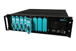
Distributed antenna systems typically consist of a main hub or head end (fed by an RF source such as a repeater or base station) connected via fiber (usually singlemode) to either one or more secondary/intermediate hubs, which in turn distribute the signal via fiber to one or more remote units. Alternatively, the head end may be directly connected to the remote via fiber without an intermediate stage. The remote unit is the last point of amplification in the system; this gear is usually a rack-mounted chassis with card slots accommodating various radio frequency cards, each supporting one frequency.
The difference between hybrid fiber/coax distributed antenna systems and all-fiber distributed antenna systems is that with hybrid fiber/coax solutions, the remote is placed in a wiring closet or intermediate distribution frame (IDF), and the “last mile” of cabling is half-inch coaxial cabling used to feed passive antennas. With an all-fiber DAS, the remote and antenna are collected (usually in the ceiling) and there is no use of half-inch coax cabling infrastructure.
Regardless of the system architecture, the challenge with most distributed antenna systems is that they frequently must be upgraded with new equipment every time a new frequency is added. Cellular carriers add new frequencies every couple of years (and even public safety system will soon be moving to 700-MHz frequencies), and this means adding new hardware and amplifiers to a conventional DAS. This is because, as mentioned previously, conventional DAS solutions use a separate amplifier to support each frequency, so they have to “stack” amplifiers in order to support more than one frequency. (Today’s demands typically require support of as many as eight frequencies.) When it becomes necessary to add a frequency to the system, yet another amplifier must be added to the stack.
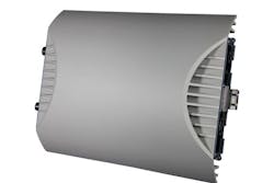
To add that additional amplifier to a conventional DAS, you may need to add another card or blade into the head end, the intermediate hub (if one is being used), and in the remote unit, assuming the remote is a chassis that is closet-mounted and can accept cards or blades. With a self-contained ceiling-mounted remote (typically found in an all-fiber DAS), you would have to insert an add-on module, or you would add a second remote. That second remote would have to be daisy-chained off the primary remote, and if that’s not possible then you would end up deploying a whole new second layer of equipment simply to support one additional frequency. And this may be the case in any event if there is no additional space (card slots) in the head end, intermediate hub, or remote chassis.
A truly wideband DAS is different; it uses a single amplifier that covers every frequency. Because of the high-power nature of this amplifier, it allows you to spread the amp’s power across multiple frequencies (and carriers using those frequencies) while being able to balance the power output at the end of the remote so that coverage is consistent for each and every frequency.
Facilities use
When deploying a DAS, space for the needed equipment is always an issue. Equipment uses space, power and cooling resources, so the size of the overall system impacts TCO.
There’s a difference in size between types of DAS solutions. Hybrid fiber coax systems in particular can be fairly large. Most hybrid fiber coax systems have a head end hub that is rack-mounted and can easily be accommodated in a standard telecom or IT room. But the remotes, which are typically 4- to 6-U-high rack- or wall-mounted units, go in the tight confines of a wiring closet. Finding the necessary space and power for these units can often be a challenge. You should also consider the amount of space the cabling takes; it spreads from the remote unit to 4-8 antenna points, and that’s a pretty heavy footprint caused by the cable infrastructure when you’re using heavy coax.
The head end is also a space consideration. Space is precious in equipment rooms and data centers, and while the head end hub of a DAS solution may not be a space issue, most DAS require attenuation panels between the carrier base station and the DAS head end to condition the carrier base station’s signal. This is necessary to ensure that the signal is of an appropriate strength so it can be fed to the DAS head end without damaging the equipment. Most DAS manufacturers now use active integration panels to reduce the amount of such “plumbing” required, and some even use direct digital interfaces so the base station can talk directly to the head end without a lot of intermediate “plumbing.” But even with these improvements, the space requirements (as well as power and HVAC) can be significant, particularly for larger buildings supporting multiple wireless operators.
Recommendations
While Category 5/6 Ethernet may be a tempting DAS cabling options because of its ubiquity, its distance and capacity constraints make it suitable only for smaller buildings and applications requiring support of only one or two wireless frequencies. As we’ve seen, while the use of coaxial cabling provides more available bandwidth, even hybrid fiber coax systems have their drawbacks in terms of cost, reach, and performance. A pure fiber cabling infrastructure offers the most advantages, particularly in terms of key attributes such as cost, performance, and flexibility.
Given the relative characteristic of cable types and DAS architectures, it seems clear that a DAS that uses end-to-end fiber connectivity and a truly wideband amplification architecture will deliver the lowest TCO. This type of system will deliver a genuinely futureproof solution, which is critical in today’s rapidly changing wireless landscape.
John Spindler joined Zinwave (www.zinwave.com) as vice president marketing and product management in November 2015. He has more than 30 years’ product management and marketing experience in the wireless and telecommunications industries. His most recent role as director of product management was with TE/CommScope, and he previously was vice president of marketing at ADC Telecommunications.


