By Cindy Montstream, Legrand North America
Beginning in August, 1994 with its first publication, TIA’s 607 bonding and grounding standard has come a long way. Originally titled “Commercial Building Grounding and Bonding Requirements for Telecommunications”, the standard was developed as a response to the need for a bonding and grounding system in the telecommunications industry. There were existing standards, like those from the NEC (National Electrical Code), that specify requirements regarding the safety aspects of bonding and grounding of equipment systems. These were not sufficient because telecommunications systems needed a bonding and grounding system for performance, not safety, since telecommunications systems operate at much higher frequencies and low voltages.
Evolving from that first revision in 1994, and then as a joint standard, the 607 standard has been restructured over the last couple of revisions to include a lot of great information including component descriptions, design requirements, and performance and test requirements. Revision C has added new information and made improvements to clarify content. This article will review these changes.
Key changes
As with all revisions to standards, the references to other standards were updated and the addendums from the previous revision B were incorporated. The following is a list of key changes included in revision C.
- The contents of Addendum 1 (external grounding) and Addendum 2 (structural metal) were incorporated.
- Terms were changed to harmonize with ISO/IEC 30129
- A new section for rack bonding busbars was added with design and installation requirements.
- An illustrative example was added for a single story large building
- Recommendations for bonding connections for separately derived systems was added
- Other design and installation recommendations
Terms simplified and harmonized with ISO
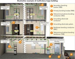
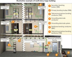
Some of the key component names have been changed to harmonize with ISO/IEC 30129. The changes help simplify some of the component names and also make them more accurate. For example, the word “grounding” has been changed to “bonding” since everything, except for the connection of the telecommunications bonding conductor to the service equipment (power) ground, is bonding. The table above summarizes these changes.
Figure 1 (page 12) shows the bonding and grounding system with most of the terms in the table. It is a pictorial representation that is similar to the example of a multi-story large building in the ANSI/TIA-607-C standard.
New sections for RBBs
In addition to changing the name, the C revision has added new sections to clause 6 (“Telecommunications Bonding Components”) and 7 (“Design“) for rack bonding busbars (RBB). Within the busbar component section of clause 6, RBB are now required to have a minimum cross-sectional area equal to a 6 AWG wire and be listed.
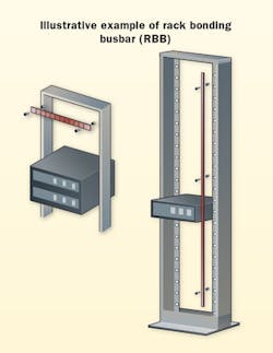
Clause 7.4 includes design and installation guidelines for rack bonding busbars, along with the connections to them. Figure 2 (below) shows an illustrative example of the rack bonding busbar (RBB). There is no specific length defined for the RBB, however, the section does require the RBB to be cleaned and have an anti-oxidant applied prior to fastening any connectors to the busbar. RBBs may be installed with a horizontal or vertical orientation as shown in the figure, using insulators that provide 0.75 inches (19 millimeters) of separation.
RBBs are recommended for cabinets and racks that need to support bonding for multiple pieces of equipment or patch panels for shielded cabling. When used, the RBB must be bonded to the rack. The telecommunications equipment bonding conductor (TEBC) connects the RBB, on the rack/cabinet, to the primary or secondary busbar in the distributor room.
Single story large building
A multi-story building has always been used to illustrate the telecommunications bonding and grounding system. Suggestions were made to the TIA TR-42.16 committee, the committee that manages this standard, to illustrate the bonding system on a large, single-story building.
Figure 3 above pictorially represents the illustration of the telecommunications bonding and grounding system in a large, single-story building that was added to TIA-607-C. Instead of having one distributor room (e.g. telecommunications room, equipment room) on the first floor, a large single-floor building may have multiple distributor rooms on the main floor, hence creating a horizontal bonding backbone topology. The primary bonding busbar (PBB) is the busbar that connects to the main service equipment (power) ground. All subsequent bonding busbars are considered to be secondary bonding busbars (SBB).
Recommendations for separately derived systems
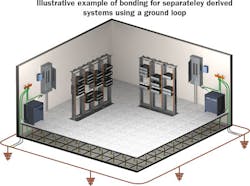
A new clause 8, External Grounding, was incorporated from addendum 1 to the previous revision. It provides additional recommendations for grounding resistance (minimum requirements are met by the use of an NFPA 70-compliant grounding electrode) and grounding electrode system design. One of the suggestions for situations in which equipment may be distributed throughout a building and may be interconnected by metallic links is to add a building perimeter ground loop to supplement the bonding and grounding system for better potential equalization.
Separately derived systems result in the same potential equalization challenges. In the Potential Equalization clause, TIA-607-C provides the design recommendations for the building perimeter ground loop. If separately derived electrical systems are present, they should be bonded to the same ground ring electrode. The concept is illustrated in figure 4 (page 14, bottom).
Additional design recommendations
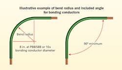
The third revision includes a number of other design and installation guidelines, too. Bend radius was added as an installation guideline for bonding conductors. The standard requires that the conductors at the PBB and SBB maintain a minimum bend radius of 8 inches (200 millimeters). At other locations, it is recommended that the inside bend radius should be as large as practical with a minimum of 10 times the bonding conductor diameter. In all cases, a minimum included angle of 90° shall be used. Figure 5 (page 16, top) illustrates the bend radius and included angle.
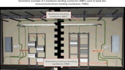
Clarification was added to emphasize that backbone bonding conductors (BBC) must be at least the same size as the largest telecommunications bonding backbone (TBB) it is connected to. Backbone bonding conductors are used when two or more TBBs are used in a multi-story building (see Figure 6, page 16, bottom).
TBBs are required to be bonded together using a BBC at the top floor and then every third floor, at a minimum. Having the BBC be a smaller conductor than the TBB impedes the bonding system like connecting two 10-inch water pipes together with an 8-inch water pipe.
As this standard matures it continually becomes better and better. Changes incorporated into this revision help to simplify and clarify the requirements and guidelines. Important content was added including the two addendums, terms were harmonized with ISO and simplified, and diagrams were improved or redrawn to eliminate interpretation errors. Other clarifications include an added requirement that patch panels, for shielded cabling, be bonded to the telecommunications bonding system and that bonding requirements apply to all metallic telecommunications pathways.
Many of the changes incorporated into this revision came from input provided to the committee. Input and participation is crucial for all TIA standards to continue to evolve as our industry evolves.
If you are interested in participating in the TIA TR-42 subcommittees, which are responsible for developing and maintaining telecommunication standards for telecommunications cabling infrastructure in user-owned buildings, such as commercial buildings, residential buildings, homes, data centers, industrial buildings, healthcare, etc., contact TIA or someone already involved in the committees like myself.
Cindy Montstream, RCDD/NTS, EE, CPLP is director of eLearning and at the data communications division of Legrand North America (www.legrand.us), headquartered in New London, CT. With a bachelor’s degree in electrical engineering and a masters of technology education, she has more than 26 years’ experience teaching technical subjects and working in the telecommunications industry. Cindy is vice chair of the TR-42.6 and TR-42.16 committees, chair of TR-42.3, and vice chair of standards for the TIA Fiber Optic Technology Consortium. In 2010 she earned her Certified Professional in Learning and Performance (CPLP) certification from the Association for Talent Development (ATD).
