By Josh Taylor, CABLExpress
With new industry standards and increased demands on data center throughput, 40/100G Ethernet will be an integral component of the next-generation data center. Implementing 40/100G Ethernet depends upon a variety of organizational factors, including existing infrastructure, budget, throughput demand and leadership priority. This article will discuss the deep impact that this network speed transition has on data center cabling infrastructure, and the decisions that organizations will need to make to accommodate these changes.
Why migrate to 40/100G?
The world revolves around digital data and its growth. We now rely on data to conduct business, engage in social activities and manage our lives. It is estimated that by 2020 the digital universe - the data we create and copy annually - will reach 44 zettabytes, or 44 trillion gigabytes.
Several other factors, including the increase in cloud storage, will drive the need for data throughput and exponential growth of information with the advent of the Internet of Things (IoT). This exponential growth in information means processing speeds have to increase as well, so as not to slow access to data. High-performance cabling that can transfer data over 40/100G Ethernet will be a necessary addition to data centers looking to keep up with this digital data growth.
Preparing for 40/100G migration
As data center speeds increase, optical loss budgets decrease. Optical loss occurs over cabling distance and at mating points where connections are made. Because most data center cabling runs are shorter distances (compared to long-haul campus runs), the inherent losses from distance in a data center are somewhat negligible compared to the losses incurred from mating points.
As connections in the data center increase to improve manageability, performance suffers. This is because added connections contribute to increased dB loss. Therefore, a balance must be maintained between manageability and performance.
Choosing the right cabling product can combat the issue of balancing manageability versus performance. Cabling products with low optical loss rates will ensure that a structured cabling environment is running at its peak. When comparing dB loss rates of cabling products, look for “maximum” instead of “typical” loss rates. While typical loss rates can allude to the performance capabilities of a product, they are not helpful when determining loss budgets.
Cabling infrastructure design
Due to the exponential port growth experienced by data centers during the last two decades, cabling infrastructure is often reduced to a cluttered tangle commonly referred to as “spaghetti cabling.” Spaghetti cabling leads to decreased efficiency, increased dB loss and more cable management challenges.
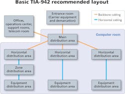
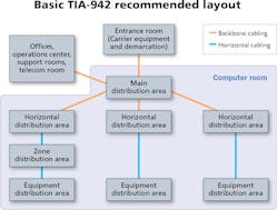
The Telecommunications Infrastructure Standard for Data Centers, TIA-942, was developed to address various data center infrastructure design topics, including the problem of spaghetti cabling. Among other aspects of data center planning and design, TIA-942 focuses on the physical layout of cabling infrastructure.
TIA-942 offers a roadmap for data center cabling infrastructure based on the concept of a structured cabling environment. By creating logical segments of connectivity, a structured cabling system can grow and move as data center needs change and throughput demands increase. Therefore, implementing a structured cabling system in accordance to TIA-942 standards is the ideal way to prepare for migration to 40/100G speeds.
The heart of a structured cabling system is the main distribution area, or MDA. All equipment links back to the MDA. Other terms used to define this area include: main crossconnect, main distribution frame (MDF), and central patching location (CPL). The principle of a structured cabling system is to avoid running cables from active port to active port (often referred to as “point-to-point”). Instead, all active ports are connected to one area (the MDA), where the patching is done. This is also where moves, adds, and changes (MACs) take place.
TIA-942 calls for the use of interconnect points, which are typically in the form of patch panels (also referred to as fiber enclosures). Patch panels allow for patch cables (or jumpers) to be used in the front of the racks or cabinets where the equipment is housed. The patch cable would then connect to a fiber-optic trunk, and then to another patch panel in the MDA.
There are several advantages to implementing a structured cabling system. First, using fiber-optic trunks significantly reduces the amount of cabling bulk both underfloor and in overhead conveyance. Implementing a structured cabling system also reduces airflow congestion, which reduces power usage.
Another distinct advantage to a structured cabling system is that it allows for modularity, meaning connector changes can be made without having to remove horizontal or distribution cabling. For example, a chassis-based switch with 100BFX ports is connected to a patch panel using SC fiber-optic jumpers. To upgrade the chassis and install new blades with LC ports, you no longer have to replace the entire channel as you would with a point-to-point system. Instead, the module within the patch panel is replaced. Underfloor and overhead cabling would remain undisturbed.
However, it should be noted that this method does add insertion loss to the channel because it adds more mating points. To offset insertion loss created by additional mating points, high-performance fiber-optic cables should be used for implementation.
Connectivity options
When migrating to 40/100G speeds, there are several connectivity options to consider when planning your cabling infrastructure.
The first uses long-haul (LX) transceivers with singlemode (SM) cabling. Data is transmitted via serial transmission. In a serial transmission, one fiber is dedicated to carry transmitting data and another fiber to carry receiving data. These two fibers make what is referred to as a “channel.” A channel is defined as the fiber, or group of fibers, used to complete a data circuit. Until recently, serial transmission has been used for Ethernet speeds up to 10G.
This setup is typically not used in data centers because it is built for long distances. It is also very expensive, despite the abundance (and therefore low cost) of singlemode cabling. In order to work effectively over long distances, the lasers used in LX transceivers are extremely precise - and expensive. This drastically increases the overall cost of an LX/SM connectivity solution.
The next option uses short-haul (SX) transceivers with multimode (MM) cabling. Data is transmitted via parallel-optic transmission. Parallel-optic transmission aggregates multiple fibers for transmission and reception. For 40G SR4 transmission, four fibers transmit at 10G each, while four fibers receive at 10G each. This means a total of eight strands of fiber will be used for a 40G Ethernet channel.
The same principle applies for 100G SR10, except the number of fibers increases. Ten fibers at 10G each transmit data, and ten fibers at 10G each receive. A total of twenty fibers make up a 100G SR10 Ethernet channel.
With the Institute of Electrical and Electronics Engineers (IEEE) 802.3bm standard update, a new connectivity option is offered in 100G SR4. This option allows for 100G Ethernet speeds using a 12-fiber MPO interface. It is the same principle as 40G SR4, but each fiber would be transmitting or receiving 25G.
These short-haul connectivity setups are more ideal for migrating to 40/100G Ethernet because they work well under the short distances found within a data center. Also, because SX transceivers use a vertical-cavity surface-mitting laser, or VCSEL, they are much less expensive than their LX counterparts.
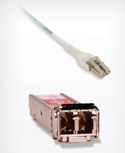
The next option features new technology. Very recently, technology advancements have been made that offer alternative options to the standard QSFP MM transceivers, with an MPO connection. These new transceivers use a duplex LC footprint - a technology that offers a significant advantage to end-users with LC connector footprints in their existing infrastructures.
A recently launched product, the QSFP-40G Universal Transceiver, not only uses the LC duplex footprint but also is universal for both multimode and singlemode fiber. This transceiver is standards-based as well, compliant with IEEE 802.3bm, so it can interoperate with QSFP-40G-LR4 and QSFP-40G-LR4L.
A newly developed bidirectional (BiDi) transceiver also uses the LC duplex footprint. The key factor for this transceiver is its use of multiple wavelengths. It uses two 20-Gbit/sec channels, each transmitted and received simultaneously.
Fiber types
If multimode cables are being used to migrate to 40/100G Ethernet, it is recommended they be OM3 or OM4 fiber, replacing any OM1 or OM2 fiber cables.
OM4, a newer fiber type on the market, has the most bandwidth and is more effective over longer distances. OM4 is highly recommended for any new installs as it provides the longest lifespan in a cabling infrastructure. OM5 fiber should be considered as well.
Back to basics: Connectors
The LC fiber cable connector is the most accepted connector used in the data center, especially for high-density network applications. The LC connector has one fiber, and is typically mated in pairs for a duplex connection.
Possibly the most drastic change data centers will undergo in migrating to 40/100G Ethernet is a change from the LC connector to the MPO-style connector.
Developed by Nippon Telegraph and Telephone Corporation (NTT), “MPO” stands for multi-fiber push-on. A popular brand of the MPO-style connector, US Conec’s MTP is often used to refer to all MPO connectors - similar to using the brand name “Band-Aid” when referring to an adhesive bandage.
What about copper?
There have been significant technology improvements over the past few decades that create the potential for 40G copper links. Choosing copper over fiber usually boils down to cost. Active copper cables with transceivers on each side that use coaxial cables are surging in the market, driven by top-of-rack architecture that uses switches at the top of a rack versus a patch panel. This can be costly, especially when considering hardware refresh rates and support windows.
For the long-term, it is clear that fiber optics will play the dominant role in data center structured cabling. Fiber has better transmission properties and is not susceptible to external interference the way the copper medium is. However, copper cabling will continue to have a role toward the “edge” of a data center structured cabling system, as well as the edges of a campus network.
Next steps
Data centers are experiencing the most significant change in cabling infrastructure since the introduction of fiber-optic cabling. No longer is it a question of if data centers will migrate to 40/100G Ethernet, but when. Installing a high-performance, fiber-optic structured cabling infrastructure is essential to a successful migration.
We covered why migration to 40/100G Ethernet is imminent, as well as the decisions data center managers will need to make to prepare for implementation. There are several next steps you can take to prepare for this drastic change.
- Determine your current and future data center needs, including throughput demand, data production rates and business-driven objectives. In what ways does your current data center infrastructure support and/or fail those needs?
- Use this information to determine when your data center should migrate to 40/100G Ethernet.
- Map out your current data center infrastructure.
- Use this map to create a plan for the hardware and cabling infrastructure upgrades necessary for migration.
- Create a plan for migration, including internal communication strategy, budget, timeline, and roles and responsibilities of those involved.
The timeline for migration is different for every data center, depending on technology needs, budget, size and organizational priority. However, educating yourself on 40/100G Ethernet, evaluating your current cabling infrastructure and beginning plans for implementation will ensure a smooth, trouble-free migration.
Josh Taylor is director of product management for CABLExpress, where he is responsible for all aspects of product design, support, market development, and inventory positions.


