By Maury Wood, AFL Test and Inspection Division
It’s mid-2017 and nearly everyone is aware that the information technology world encircling us is simultaneously getting both faster and denser. Bits of data are flying through optical network links at rates of 100 billion bits per second and higher, and the feature sizes in the network processor chips at the ends of these network links continue to shrink, as roughly and famously predicted by Gordon Moore. Multifiber connectors such as MPO, MT, and MXC are putting more and more less-than-human-hair diameter glass fibers into tighter spaces. With single MPO connectors increasingly using 16 fibers at 25 Gbits/sec per fiber, the asset value of these 400-Gbit/sec short-reach Ethernet links is exceedingly high, making data center infrastructure equipment failures due to connector contamination completely unacceptable to savvy management teams. Microscopic connector endface dirt and debris cause light reflections and attenuation - the enemies of optimal optical signal transmission.
Thankfully there now exist excellent quality and easy-to-use tools for inspecting and cleaning fiber endfaces. In particular, the brief history and evolution of fiber microscopes shows a compelling level of innovation, in terms of optics, electronics and software.
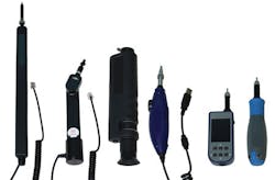
To aid our survey and history of fiber inspection tools, there are several classification distinction, as follows.
- Viewing method - direct or indirect path
- Imaging method - optical or electronic
- Image storage - internal or external
- Focus - manual or automatic
- Image view screen - integrated or external
- Connectivity - wired or wireless
- Power - battery or tethered
- Command and control - local or network remote/cloud
For the most cost-sensitive applications, as well as specialized use cases, handheld optical microscopes with direct viewing paths are available. Direct view fiber microscopes require infrared safety filters, are focused manually, use batteries for endface illumination, and typically offer 200x magnification levels. They have largely fallen out of favor, as they do not allow for the documentation of endface surface conditions or objective standard-compliant pass/fail criteria, such as IEC 61300-3-35 or IPC-8497-1. Direct view microscopes impose a legal liability risk, due to improperly installed infrared safety filters leading to end-user eye damage. Also, these older-style optical microscopes cannot leverage the enormous economics of scale of higher-resolution CMOS image sensors, ARM Cortex embedded processors, low-power semiconductor flash memory, and WiFi/Bluetooth transceiver chipsets driven by the smartphone industry. Furthermore, optical microscopes are only useful to inspect exposed ferrule connectors on patch cords, test jumpers and cables; they cannot easily be used to inspect connectors in bulkheads and distribution frames, due to their size/shape/form factor, weight and fragility.
The debut of digital
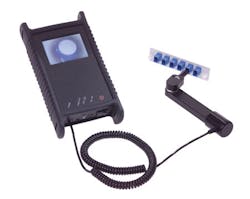
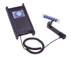
About 15 years ago, the first indirect view “digital” fiber scopes appeared, using solid state CCD image sensors. This was before the emergence of standardized, high-volume consumer-oriented data interface standards such as USB and FireWire, so the first digital fiber scopes used proprietary data formats on a variety of connectors, such as RJ11 modular telephone jacks and plugs. None of these early inspection instruments had on-board image storage or image processing, since the embedded microcontrollers of the day were too large physically and power hungry. As one would expect, these probes had manual focus wheels, and were remotely powered. There were no software deliverables associated with these early inspection systems. Over time, suppliers developed large portfolios of modular adapter tips for their probes, allowing users to inspect LC, SC, FC, ST, MU, E2000, Biconic, ELIO, SMA 905, LEMO, LX.5, TFOCA II, OptiTip and eventually multifiber MPO/MTP connectors, using both flat and angled ferrules.
About five years ago, the first wireless fiber inspection probes became available. WiFi and Bluetooth transceiver modules became small enough, cheap enough, and low-power enough to embed into handheld fiber inspection units. Of course, CMOS image sensor resolution has increased dramatically over time, and flash memory has become affordable in high-density gigabit configurations. Cell phones drove the development of very-low-power ARM Cortex-M microcontrollers capable of real-time digital processing of fiber endface images, enabling autofocus and auto pass/fail algorithmic inspection.
Innovation continues
Today, the innovation in this growing specialized market space continues. There are now inspection probes with integrated LCD screens with QVGA resolution and aspect ratio (320 by 240 pixels, 4:3), driven by simple graphical user interfaces (GUIs) that focus on ease-of-use and speed-of-use. Captured image resolution of 640 by 480 VGA in JPEG format is common. Batteries are rechargeable of course, often using ubiquitous USB chargers. Internal storage of thousands of images is typical, as is autofocus and IEC 61300-3-35, IPC-8497-1, AT&T-defined and user-defined auto pass/fail analysis. “Headless” probes with no screen and a minimum of buttons and indicators, but with WiFi wireless interfaces (for still and motion image data transfer plus command-and-control) are helping to make today’s inspection probes more cost-effective than ever. But the biggest recent enhancement to fiber-optic inspection systems is the addition of richly featured software ingredients.
It can be safely assumed that nearly all fiber installation and maintenance technicians have access to a smart device (smartphone or tablet), either through their employer or their own personal device. Given the ubiquity of smart devices, and their incredible performance (screen resolution, graphics rendering, multi-modal local and wide area wireless connectivity, internal memory capacity, powerful operating systems with elaborate application software ecosystems, etc.), it is compelling for suppliers to utilize these devices to augment the fiber inspection system user experience.
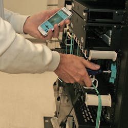
Self-contained inspection probes with integrated screens, and internal image storage and processing functions can utilize either Bluetooth or WiFi to connect to smart devices and the inspection apps they run. Bluetooth has sufficient over-the-air bandwidth to support the rapid transfer of endface still images and analysis overlay graphics (typically GIF files). However, Bluetooth does not have sufficient bandwidth to support the real-time “streaming” of full-resolution endface motion images (MJPEG format typically). So headless inspection probes without integrated image storage and pass/fail analysis processing must use WiFi (typically 2.4-GHz IEEE 802.3b/g/n) to preserve a responsive and interactive user experience.
Wireless equipment
While wireless connections to smart devices running apps is here to stay in the fiber inspection world, there are relative merits to probes with integrated displays versus headless probes that rely on external “smarts.” For example, some data centers and other fiber facilities prohibit any radio frequency (RF) transmissions, making the use of Bluetooth and WiFi impossible. And because smart devices do not always implement the host type USB interface (they may only implement the device type USB interface), and probes also implement the device type USB interface, wired or tethered USB connectivity to a smart device may not be possible. Some suppliers now offer “no wireless” self-contained probes that can be used in RF secure network facilities.
The other challenge with smart device paired probes is the fact that these systems tie up both hands of the operator - one hand to hold the probe and the other hand to hold the smartphone or tablet. When climbing ladders, for example, many technicians appreciate having a hand free, and thus prefer self-contained inspection probes. Of course, one advantage of tetherless RF connectivity is that the smart device may be located many meters away from the probe, enabling the potential for much higher mobility. Finally, an advantage of headless probes with no display is that their form factor (length, width, height and weight) can allow much easier access to densely populated fiber distribution frames or transmission equipment with high front panel port density. Some headless probes include four-color LEDs to indicate power state status, inspection pass or inspection fail status, and “no fiber detected” status. Headless inspection probes are an excellent match with cloud-based workflow management solutions, since cloud infrastructure provides unlimited storage with incorruptible inspection report security, plus the ability to flexibly rerun pass/fail analyses in the future as international endface cleanliness standards are updated.
There are some convenience and usability features to consider when purchasing a fiber inspection probe. Can the probe or supporting software generate PDF file inspection reports and make the export of these reports easy for novice users? Can the inspection probe resolve endface debris particles down to 1 micron feature size using magnification power of 400x or higher? Do the probe field-of-view dimensions support the singlemode and multimode fiber types to be used in the targeted application? Are the inspection apps compliant to the iOS and/or Android operating system revision in use by your organization? Does the inspection probe meet all required safety and compliance certifications? Is the probe battery removable if needed to meet air transport safety requirements? Does the supplier provide a device warranty that meets your organization’s expectations?
With data rates in data center optical Ethernet links looking forward to 200G, 400G and even 600G, there is a great deal of interest among Internet content/service providers to assure their facilities have microscopically pristine optical connections, to guarantee network reliability and performance. The fiber inspection equipment suppliers have responded to this demand with innovative new products, some of the characteristics of which have been covered in this short article.
Combined with an array of specialized and effective fiber connector cleaning products, the future is bright for inspection system end-users and their service provider customers.
Maury Wood is product line manager for WDM900, cleaning and inspection products at AFL’s Test and Inspection Division in Lowell, MA (www.aflglobal.com).


