Network consolidation points facilitate change with minimum disruption.
Jack G. Sheppard
Some cabling projects start out very simply but balloon into much larger jobs. About two years ago, I was involved in such a project. The client contacted me about a classified local area network (lan) that was obsolescent and likely did not meet security requirements. My assignment was to design and provide a statement of work that an implementation contractor could then use to upgrade the lan. As frequently happens, the client changed the requirements in midstream, resulting in a much bigger project than originally envisioned.
The client`s facility occupied an open-bay space with dropped ceilings in a concrete building approximately 110 feet wide by 308 feet long. The space was divided lengthwise by walls forming a hallway. Support pillars 2 feet square were spaced along the length of the building at 20-foot intervals. Telephone service was fed from two telecommunications closets (TCs) over uncategorized unshielded twisted-pair (utp) cables installed in a two-level, above-ceiling cable-tray system. Electrical cables were installed in a separate above-ceiling tray system. A central room housed classified computers. Terminals throughout the facility connected to these computers via a rat`s nest of coaxial cables, which were also installed in the above-ceiling trays. The workforce sat in modular furniture pods consisting of five triangular spaces collected around a central utility-access member. The workers sat nose-to-the-center, backs to the open area. Electrical and communications cables fed from above-ceiling trays down the access member to outlets in the individual worker modules.
The initial design
A brief check with the security authorities determined that fiber-optic cabling would be required for the accreditation of classified lan transmission media placed in above-ceiling trays. The driving issue was vulnerability to tapping, not compromising emanations. Therefore, the classified lan had to be based on optical-fiber distribution. All classified lan traffic was homed to the central computer room, so a centralized fiber design was the logical choice. The client was concerned about maximizing network performance, so switched Ethernet was selected, with servers connected to the network at speeds of 100 megabits per second. The worker "penta-pods" were ideal for a multiuser outlet design, so the initial gross design flowed logically from facility attributes and client requirements as a switched, centralized fiber network with multiuser outlets.
This client`s facility shared a large building with other entities. Under an overall networking initiative, a Xylan switch had been selected and was being implemented for network switching. This choice was made, partly because of the local pool of expertise and also because of some useful security provisions inherent with the Xylan product.
While servers in the same room as the switch could use copper cabling, connections made via cabling installed in above-ceiling trays had to use fiber-optic cabling. But, at the time of the initial design (in 1997), the port density of fiber switching cards was low and per-port cost was high. Consequently, the network switch was designed with a mix of two 8-port 100Base-TX cards and six 32-port 10Base-T cards, resulting in 16 100-Mbit/sec ports for servers and 192 10-Mbit/sec ports for workstations. The Cabletron emc38-12, a 12-port 10Base-T-to-10Base-FL media converter, was selected to provide conversion between the copper switch ports and the fiber cables to be used in distribution. The design called for 16 of these converters to be located in the computer room in a rack adjacent to the switch rack. The Cabletron emc38-12 uses 50-pin telco connectors for the 10Base-T interface and ST connectors for the fiber interface. Interfacing the switch to the converters required 16 "spider cables" with a 50-pin telco connector on one end and 12 8-position modular connectors on the other end. Today, fiber ports have higher density and lower per-port cost, so a new design would likely use fiber switch cards directly.
The client wanted fiber connectors that were simple enough for in-house staff to install, meaning that the process had to be simple and require minimal skill. After a survey of the technology, I settled on the Siecor 95-000-40, an SC connector that installs mechanically, with no polishing or adhesives, using a simple tool and procedure.
Space in the central computer room was very limited, so I had to confine the fiber termination and management to a single cabinet. After surveying the market, I settled on the Siecor cch-04u fiber-management housing and the Siecor cch-cp12-57 fiber-management panel. These panels support 12 SC connectors, and the housing supports 12 panels, giving 144 SC connectors in seven vertical inches of a 19-inch rack.
It was intended that the fiber cables run from the management cabinet in the computer room via above-ceiling trays to the individual "penta-pods," drop down through the central utility column, and terminate on multiuser outlets. However,...
"Oh, by the way..."
The client suddenly decided he didn`t like the penta-pods, which were almost 10 years old and getting a bit scruffy. The workers didn`t like them, either, because they felt exposed, and people were always stopping by and starting up bull sessions. The client decided to convert to conventional rectangular cubicles and replace the carpets in the process. Further, the power system was a mess, and coffee makers frequently caused computer reboots. "And while we are talking about computers, shouldn`t we replace the Intel 286-based computers and MultiMate software with more up-to-date Windows machines with Microsoft Office software? And we`d just as well replace all of the 286-based servers with real servers, as well. Also, in addition to the classified lan, we want all of the cubicles to have an unclassified lan port." Back to the drawing board.
Several things changed with the move to rectilinear cubicle groups. First, without some pretty good cable-stretchers, we weren`t going to be able to use the existing copper transmission medium for voice. Further, the requirement for unclassified lan ports in all cubicles meant fielding a complete second lan. Finally, there were already rumblings that a second major shuffle of personnel and work areas was just over the horizon.
The need for flexibility in positioning the cubicle clusters without replacing a lot of cable led to the use of a consolidation-point topology. The concrete pillars inherent to the building conveniently defined zones. Cubicle groups had to fit between these pillars. Therefore, the pillars were selected as the locations of consolidation points. Fiber cables were re-homed to pillar-mounted, below-ceiling cabinets with the capacity for 48 terminations. Telephone and unclassified lan cables were also homed on termination cabinets, but these were placed on the pillars above the ceilings. Telephone and unclassified lan cables, both using Category 5 utp, were homed to the nearest TC. From the consolidation points, drop cables--both copper and fiber--were run through furniture channels to outlets.
No change was required in the switch, converter, and fiber-management package for the classified lan. But, the fiber cables had to be resized. Based on two outlets per cubicle and a maximum of eight cubicles per cluster, we settled on 36-strand cables. Siecor connectors and termination panels were retained at both ends. The telephone and unclassified lan distribution used conventional Category 5 cables terminated on 110 blocks at the TCs in accordance with bicsi (Tampa, FL) practices.
Each cubicle was equipped with two outlets, each equipped with one telephone jack, one unclassified lan jack, and one classified lan SC pair. Zipcord drop cables entered the furniture group from the consolidation points through vertical utility poles and were distributed through the furniture in utility channels inherent to the furniture. If the furniture groups must be moved or reconfigured, the drop cables may have to be replaced, but the rest of the infrastructure will remain unaffected.
The client purchased a complete inventory of Dell desktop computers with 300-megahertz Pentium processors, 256 megabytes of ram, 8-gigabyte hard drives, and Microsoft Office Pro. To interface these computers to the lans, I specified the Allied Telesyn at-2450ft/sc network interface card. This interface card has both 10Base-T and 10Base-FL jacks, so the one card could be used for all desktop computers. The client also purchased an inventory of Dell servers. For these, I specified the AT-2560 family of Fast Ethernet cards.
Since some of the unclassified lan ports were fed from one TC and the rest from the other, a central switch could not be used conveniently. Instead, a Xylan Omni-5wx switch was located in each TC, and the two switches were interconnected using 100Base-TX, providing a transparent switched environment of high capacity. As in the case of the classified lan, 32-port 10Base-T cards were used in the switches for workstations and 100Base-TX cards were used for servers. One of the 100Base-TX ports was connected to an external backbone service via a firewall to provide access to the Internet and other external services.
Project implementation
The client selected a prime contractor. I had written the requirement into the statement of work, so the prime contractor`s site manager was a registered communications distribution designer (rcdd). The prime contractor selected subcontractors for electrical, communications, modular furniture, and construction work. I was retained as a consultant during the implementation phase. The client required that the carpets be replaced, the walls be stripped and painted, furniture installed, all networking installed, separate power provided for the computers, and the workers relocated into their new cubicles without shutting down the operation of the organization.
The prime contractor laid out a phased plan for the entire facility, based on upgrading a unit consisting of two of the 20-foot sections on one side of the hallway at a time. First, the communications subcontractor installed the new switching, put in the new cabling in the overhead trays, terminated the new cabling at the consolidation points, and prepared for cut-over. The electrical subcontractor did likewise. Once this phase was completed, the personnel in the two sections were moved into spaces empty due to vacations, illness, or personnel turnover, and they continued to work. The construction subcontractor then stripped and painted the walls and laid carpet tiles. The furniture subcontractor installed the furniture, and the communications and electrical subcontractors extended drop cables from the consolidation points into the furniture and terminated them on the outlets. The prime contractor unboxed the new computers, installed them in the cubicles, connected them to the new network, tested them, and installed the telephones.
At this point, the previously displaced workers moved back into the area and occupied their new cubicles. This process typically took two weeks per unit. The project was completed on schedule with minimal disruption of the client`s operation.
The new networks began going into service in January 1998 and were completed in the late spring. To date, there have been no failures of any of the communications, whether switching electronics or distribution cables, either copper or fiber. The client is currently reorganizing around a new business initiative and plans to reshuffle personnel and add some major computer systems. I`ve been retained as a consultant for this action, but except for some design for the new computers, I don`t have much to do.
The consolidation-point design of the overall facility is completely flexible. Once the client decides where the modular furniture ends up, the same prime contractor and the same rcdd site manager will extend drops from the consolidation points into the affected clusters. Business will go on with minimum disruption, which is the way it is supposed to be with modular furniture fed by a consolidation-point topology.
This article is based on a presentation made at the bicsi Fall Conference, held September 1998, in Las Vegas.
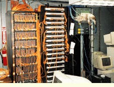
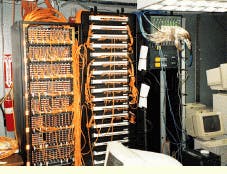
The central equipment as it appeared late in the installation phase: (from left to right) the fiber-management cabinet, the converter rack, and the rack housing the single Xylan Omni-9wx switch. The fiber-management cabinet can be locked to prevent unauthorized personnel from changing the connections.
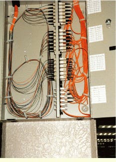
A classified lan consolidation point is mounted and cabled on a pillar.
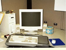
The new cubicles have two outlets, each equipped with one telephone jack, one unclassified lan jack, and one classified lan SC pair.
Jack G. Sheppard, Ph.D., professional engineer, and rcdd, is an information-systems engineering consultant in Sierra Vista, AZ. He can be contacted at [email protected].


