From the October, 2013 Issue of Cabling Installation & Maintenance Magazine
Familiarity with test standards is critical to ensuring performance in high-speed fiber-optic networks.
By Mark Miller and Run Ron, AFL Noyes Test and Inspection Division, on behalf of the TIA Fiber Optic Technology Consortium
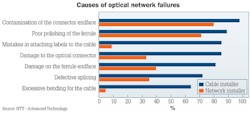
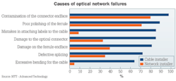
Controlling network loss has become increasingly important as loss budgets get smaller and demands on networks increase. High losses and optical network failure are often caused by contaminated, damaged or poorly polished connectors, poor splices, and micro or macrobends introduced in shipping or installation. The best way to keep your network running efficiently? Test and inspect.
Before we go on to the reasons for testing fiber networks, the types of testing needed, and how to perform this testing, remember that safety is paramount and keep the following in mind.
Laser eye safety--Do not look directly into lasers on network equipment or test equipment.
Fiber scrap and shards from fiber preparation--These must be handled properly to avoid punctures and cuts.
Ensuring all systems are powered off--Unless specifically testing a live system, all network equipment should be shut off.
Inspection testing
The leading cause of optical network failures is contamination of connector ends. It is also something installers can prevent by properly cleaning all endfaces before mating them to their networks. Proper cleaning minimizes damage to connectors and equipment, helps provide accurate loss measurements and ensures the network will operate properly.
Use a digital fiber inspection probe to look at connector ends for contamination and damage such as dirt, oil, scratches and epoxy. It is important to do this because dirt can be transferred from a contaminated connector to a clean connector, and may even cause scratches in the clean connector. All connectors--even brand new jumpers with a factory finish--should be cleaned prior to mating to prevent dirt moving from one connector to another; connector contamination as small as 0.001 mm can cause high loss and poor reflectance.
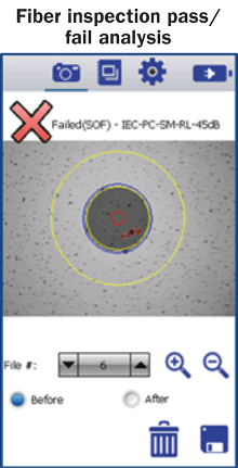
The core size in an optical fiber is quite small; in a singlemode fiber it is only 8 to 10 microns in diameter, and the most-popular multimode fibers have core sizes of only 50 microns. It does not take much dirt to contaminate the endface, jeopardize the quality of the connector and limit the capabilities of your network. Just touching the end of a connector can leave a film of body oil. Some digital inspection probes analyze the size, type and number of contamination "events" present on a connector end, and provide a pass/fail result based on a standard such as IEC 61003-3-35.
A basic fiber test consists of using a visible light source to check for end-to-end continuity of a fiber, and connector polarity. This type of tester is called a visual fault locator (VFL), and uses a visible red laser to visually detect breaks in continuity caused by fiber bends, breaks and faults. It can also be used to check the polarity of duplex and MPO cables.
Tier 1 testing--Link insertion loss
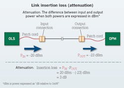
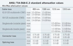
The insertion loss of a fiber is the measurement of the attenuation--or the light power loss--that occurs between the two ends of a fiber link, when light travels through it from end to end. Attenuation is measured in decibels, and it limits the distance that a signal can travel within the fiber. Some attenuation is inherent in the glass itself. Most of the attenuation is caused at the connection points. And some can be induced if the fiber is bent or crushed.
Attenuation is tested using an optical light source (OLS) and optical power meter (OPM). These two pieces of equipment together are referred to as an optical loss test set (OLTS). The insertion loss (IL) is the difference between the input power level (reference level) and the output power (measured level). In the figure titled "Link insertion loss (attenuation)," the reference power level is Pin, and the output power is Pout. (IL=Pin-Pout)
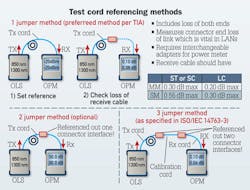
In practice the OLS and OPM are connected to the link using patch cords. To get an accurate IL measurement of the link only, you must take into account the loss added by the patch cords. There are several ways to do this. These methods are specified in the TIA-568-C standard and ISO/IEC 14763-3 standard as 1-jumper, 2-jumper and 3-jumper.
Depending on which method you choose, the losses associated with the connections at the ends of the fiber under test will be either included or excluded. The 1-jumper method is the preferred method in the TIA standard, while the ISO standard designates the 3-jumper method as preferred.
The 1-jumper method is the most popular test as it includes the loss of the connections at both ends of the fiber under test. Because most of the loss on a fiber link is the result of those connections, this is perhaps the most-accurate measurement technique.
The 2-jumper method references out one of those connections and includes the loss of only one connection of the fiber under test, so it gives you only a partial picture of the loss measurement values.
The 3-jumper method is used when the fiber type in the test cords do not match the fiber type in the link. This situation could occur when testing multimode networks, where various types of cable are used. The 3-jumper method also requires special low-loss test cables and a third calibration cable. The OPM will have a "set reference" function that will null out the loss of the TX, RX and calibration cables, as required by the method being used.
No matter which method is used, the TX test cable must remain connected to the OLS after the referencing step is performed. If this connection is broken, you need to repeat the referencing step.
When performing Tier 1 testing on multimode networks the test cable connected to the OLS must be mode conditioned to ensure accuracy. Mandrel wrapping is a time-proven method of removing the cladding and loosely coupled/higher-order modes when used with an overfilled (Category 1 CPR) light-emitting diode (LED) source for multimode testing. Five turns are wound around the mandrel specified for use with the fiber/cable under test. Fiber should be standard OM fiber, not bend-insensitive fiber, because bend-insensitive fiber has different bend characteristics and does not respond to mandrel wrapping in the same manner as standard fiber.
Mode conditioning is usually not required when testing singlemode fibers. However, for very short distances, multiple modes may be transmitted. So it is good practice to include a 30-mm loop in the TX cable to remove these modes.
Certification testing
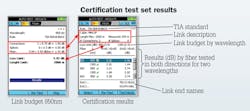
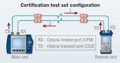
A certification test set is a specialized Tier 1 tester that provides additional functionality over an OLS/OPM setup. Besides basic attenuation measurements, the certification tester measures fiber length, and checks continuity and polarity. A key feature is the ability to test two fibers at one time in both directions. This speeds up the testing process. Some network certification standards require bidirectional loss measurements. Certification test sets allow the user to choose pass/fail criteria based on industry standards, and to create a finished report. A certification test set consists of two units, both of which contain an OLS and OPM. The two units communicate with each other over the two fibers being tested and an automatic test is run.
Prior to testing, the user enters information about the fiber under test, including the number of connections and splices, and chooses the appropriate pass/fail rule and jumper reference method. Users at each end of the link are prompted to swap position of the TX and RX test cables to complete the bidirectional test. The equipment calculates the link budget and the test results are compared to the link budget for an indication of pass or fail.
Tier 2 testing with OTDR
In addition to the loss measurements provided by Tier 1 testing, there are ISO/IEC and ANSI/TIA/BICSI standards that include measurements that can only be done using an optical time-domain reflectometer (OTDR). The OTDR is also the best fault location tool available. It provides a detailed look at events along the entire length of the fiber.
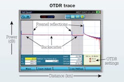
The OTDR sends pulses of light down the fiber under test. As the light pulse travels down the fiber, some of the energy is returned to the OTDR due to backscatter (known as Rayleigh backscatter). The backscatter occurs continuously along the fiber due to imperfections in the fiber. It is the primary source of loss in the fiber. Shorter-light wavelengths scatter more strongly, and therefore fiber has more insertion loss at shorter wavelengths. For example, multimode fiber has more loss at 850 nm than at 1300 nm. The OTDR measures the intensity of the backscattered light as a function of time, converts this to distance, and displays this visually. It also displays the total loss of the fiber (in dB) and the loss per distance (in dB/km).
In addition to Rayleigh backscatter, light is reflected from points in the fiber where there are changes in the fiber's index of refraction (Fresnel reflections). Events along the fiber that cause these reflections include: the end of the cleaved fiber, two mated connectors, an unterminated connector, a mechanical splice, and an air gap at poorly mated connectors.
These events appear as sharp spikes in the OTDR trace. The height of the spike, relative to the adjacent backscatter, is the event's reflectance. Reflectance is the ratio of reflected light to incident light at a single point. High reflectance is a concern in LANs operating at 10, 40 or 100 Gbits/sec, for long-haul networks, and networks carrying analog video.
Reflectance is directly impacted by termination technique. Reflectance is measured in dB, and a typical reflectance value for mated connectors is in the range from -35 dB to -65 dB. The more negative the number is, the less energy is being reflected back to the OTDR, meaning better network performance.
Another measurement provided by an OTDR is optical return loss (ORL). ORL is the ratio of the average reflected light from the entire fiber, measured at the launch point, to the average incident power level injected into the fiber at the launch point. A high reflectance at the far end of a long fiber won't contribute much to ORL. A high reflectance at the near end of a long or short fiber will be the primary contributor to the overall ORL.
Besides loss measurement of the entire fiber, an OTDR is also able to measure the loss of a section of the fiber by moving cursors to the desired points in the trace. Note that the end-to-end loss measurement provided by an OTDR is not as accurate as a Tier 1 insertion loss measurement.
The OTDR is used for troubleshooting and locating faults such as fiber breaks and connector checking. When a cable is initially installed and certified, a baseline trace is taken and kept for reference. During troubleshooting the expected baseline trace is compared to the current trace.
Many OTDRs automate event detection and measurements, speeding up the Tier 2 measurement process and allowing less-experienced technicians to fully use the capabilities of an OTDR. The OTDR displays a table of events indicating the type of event and its associated loss and reflectance measurements, as well as a summary of end-to-end loss and ORL.
To ensure performance levels as network speeds increase to 10-Gbits/sec and higher, it is vital to start with clean connectors and to have a complete set of fiber measurements--first as a baseline to verify the quality of new installations, and then as a way to diagnose potential problems that might occur with your network. Industry standards provide clear guidance for fiber inspection and Tier 1 and Tier 2 measurements. It is important that all test personnel become familiar with the standards and the proper equipment needed to install and maintain today's networks. ::
Mark Miller and Run Ron, both with the Noyes Test and Inspection Division of AFL (www.aflglobal.com), authored this article on behalf of the TIA Fiber Optics Technology Consortium (www.tiafotc.org).
Archived CIM Issues
