It takes more than just thicker wire to support next-generation Power over Ethernet.
The combination of standards, codes, and best practices for remotely powering network devices presents significant challenges for user organizations as well as system specifiers, designers, and installers. Recently developed standards and codes have sought to address the means of most-effectively and most-safely deploying twisted-pair cabling to support remote powering. At the same time, manufacturers of cable and connectivity have done their own development, to offer cabling components that are up to thetask.
Today, the material composition of a twisted-pair cable intended to support remote powering is different in several ways from the material composition of components solely intended to support 10/100/1000Base-T. Similarly, the design and composition of a connector—particularly a jack—that will support remote powering incorporates engineering that did not need to be considered for gig-speedsupport.
Sparking a conversation
The extent to which cables’ and connectors’ physical characteristics affect remote power or Power over Ethernet support have been known for years. In a technical paper published in 2015 titled “Power over Ethernet with Panduit Copper Cabling,” Panduit explained, “Cables and connectors, by themselves, can handle the 960 mA current and 71W of power [anticipated to be specified in IEEE 802.3bt]. The concerns with running PoE in cables has to do with heat and temperature rise that occur when the cables are bundled, and the concern with connectors is arcing that occurs when a plug is removed from a connector with livePoE.”
The paper also explains, “An electrical arc (spark) naturally occurs most times when removing a plug from a jack with PoE running. The arc poses no danger to the user, and it is often difficult to notice. However, it can damage the points on the jack and plug contacts where it occurs. Connectors must be designed so the location damaged by the arc is not where the plug and jack mate. The IEC developed test methods IEC 60512-9-3 and IEC 60512-99-001 to address this particular issue.” The paper stated that Panduit’s plugs and jacks are designed to pass both test methods “to ensure that when arcing occurs, it will not damage the critical plug and jack matingpoint.”
Siemon also published documents on the topic. One, titled “The Effects of Spark Gap Erosion Caused by Unmating Under PoE Load” and published in 2013, points out, “Contacts in network connecting hardware such as RJ-45 jacks and plugs are carefully engineered and plated, typically with gold or palladium, to ensure a reliable, low-resistance mating surface. Unmating a jack-plug connection while transmitting PoE produces an arc within the spark gap as the current transitions from flowing through a conductive metal to air before becoming an open circuit. While the level of current associated with the arc poses no risk to humans, the arcing creates an electrical breakdown of gases in the surrounding environment that erodes the plated jack-plug contact surfaces at the arcing location.” The document describes and displays contacts that have suffered erosion caused by sucharcing.
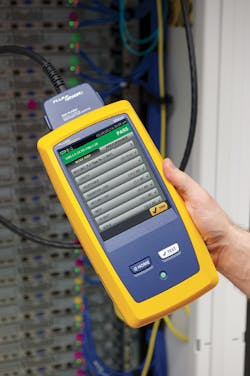
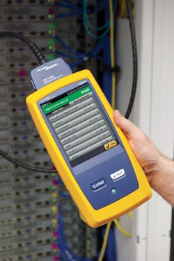
The Fluke Networks DSX Series CableAnalyzer can certify the DC resistance performance of installed cabling systems. Recently the DSX Series incorporated limits for the PowerWise and Clarity system from Superior Essex and Legrand.
“When spark gap erosion occurs in the area of the fully mated position on an RJ-45 connector, the result is an unreliable connection due to the contact surface damage. This can cause degraded network performance and increase bit error rates. Some connecting hardware manufacturers have succeeded in ensuring that arc location during the unmating cycle is separate from the fully mated position. While this may hold true for jack contacts, their contact geometry does not ensure that erosion on plug contacts is also away from the fully mated position. Erosion on either the jack or plug contacts results in an unreliableconnection.”
The document then describes the particular shape of contacts Siemon uses in its Z-Max, Max, and Tera brand jacks—a crowned shape—explaining this shape “ensures that arcing will occur in the initial contact ‘wipe’ area on both jack and plug contacts, and will not affect mating integrity in the fully mated contactposition.”
TSB-184-A
Several technology and standards developments have taken place since the publication of those documents by Panduit and Siemon. In March 2017, the Telecommunications Industry Association (TIA) approved and published Telecommunications Systems Bulleting TSB-184-A Guidelines for Supporting Power Delivery Over Twisted-Pair Cabling. That TSB makes several recommendations, including the use of Category 6A or higher-performing cabling for any new installation that will deliver remote power, and the use of connecting hardware that complies with IEC 60512-99-002 test requirements. (The “-002” document was published after Panduit authored its document citing the “-001” standard.)
TSB-184-A also explains that thermal dissipation—the dissipation of heat in cable bundles—can be improved if users select cables with several physical characteristics, including: improved thermal conductivity, improved heat transfer coefficient between cable materials, improved heat transfer coefficient between cable jacket and air, metallic elements such as a shield or screen, and a largerdiameter.
The TSB also includes bundling recommendations, advising against bundling altogether when that can be achieved. When bundling is necessary, limiting any bundle to 24 cables in a typical pathway can limit temperature rise. It also recommends separating large bundles into multiple smaller bundles to limit temperaturerise.
Another ingredient in the stew of cabling’s support for remote powering is the LP (Limited Power) cable certification, which Underwriters Laboratories (UL) introduced in 2015. UL says the program is meant “to simplify cable choice and installation considerations. The ‘-LP’ cable designation indicates that the cable has been evaluated to carry the marked current under reasonable worst-case installation scenarios without exceeding the temperature rating of the cable. The certification takes into account large bundle sizes, high ambient temperatures and other issues related to environmental effects, such as enclosed spaces orconduits.”
In the 2017 edition of the National Electrical Code, LP cable is included as an alternative to specific bundling requirements. We at Cabling Installation & Maintenance have covered that topic several times, and undoubtedly will again in futureissues.
Vendor developments and partnerships
Over the course of a year, Superior Essex introduced two cables that were engineered to support high levels of remote powering. It debuted the PowerWise Category 5e Cable, for PoE applications in September 2015 and the PowerWise I/O 1 Gigabit 4PPoE CRM/CMX Cables for indoor/outdoor PoE applications in September 2016. At the time of the 2015 introduction, the company explained the PowerWise Category 5e achieves 88-percent power efficiency for 802.3at and future 802.3bt applications. “This improved power efficiency is due to the fact that 22-gauge copper wires are 59 percent larger than the 24-gauge copper wires typically used in Category 5ecables.”
The company’s vice president of marketing, Will Bryan, said, “As the market makes plans for a world of devices that require up to 960 milliamps of current over four-pair data cables, there is legitimate concern over the potential danger posed by the high temperature increases observed in 24-gaugewires.”
When PowerWise I/O was introduced a year later, Bryan noted the cable supports PoE in outdoor spaces for applications such as access control and outdoorWiFi.
More recently, Superior Essex and its channel partner Legrand announced, along with Fluke Networks, that the Versiv Cabling Certification System supports Legrand’s Clarity cords and jacks, as well as Superior Essex’s PowerWise cableproducts.
When that announcement was made in February 2018, Fluke Networks’ global marketing director Harley Lang commented, “As the industry leader we are on the ground floor working with other companies and experts in our industry in developing new network standards and requirements. Our Versiv products have always had the capability and flexibility to test a cabling system’s ability to support PoE. As a result, Fluke Networks is ready to support innovative manufacturers like Legrand and Superior Essex as they roll out cutting-edge network products for PoE and other standards.” Fluke Networks provides certification products and services with the capability to test and certify all IEEE standards and requirements for 802.3btinstallations.
The three companies combined to produce a technical paper titled “Considerations for the Design and Field Testing of an Optimized High-Power PoE Cabling System.” Subtitled “Why comprehensive testing for DCR [direct current resistance] unbalance is critical,” the document points out that when published, the IEEE 802.3bt specifications will include DCRrequirements.
“Compliance to DCR ensures requirements that power delivery does not degrade data performance, while maintaining a consistent voltage between two pairs,” the paper says. “In order to meet the requirements outlined in IEEE 802.3bt Draft 3, DCR should not exceed 21 ohms. The difference in resistance between two pairs must not exceed 200 milliohms or 7.0 percent, and the difference between two conductors of the same pair may not exceed 100 milliohms or 3.0percent.
“The standard also recognizes that field measurements may have accuracy limitations below 200 milliohms. These standards exist to prevent DCR unbalance, which can be caused by faulty cable manufacturing or poor installation practices, and sometimes even by a cable’s specific wire gauge. DCR testing measurements are conducted by the cable manufacturer; lower DCR ratings indicate that a system is better protected than one with a higher rating. Products manufactured with attention to DCR tend to have longer lifespans and lower costs because balancing power and data delivery prevents an excess of power on a single trace, and offers more power efficiency without data degradation. When evaluating a PoE system, it’s important to analyze DCR unbalance within a pair, pair-to-pair, and overall DCR to ensure the optimum delivery of power anddata.”
Deploying a balanced twisted-pair copper cabling system that will be able to support the delivery of remote power at IEEE 802.3bt-specified levels requires thoughtful preparation at every step. It involves the product design and engineering steps taken by manufacturers, the specification of appropriate products with sufficient capabilities, the design and installation of cable runs including bundling considerations, testing of the installed circuits—and that’s not to mention user-specific needs and preferences. The technology behind cabling systems has evolved and improved over the past few years to equip designers, installers and owners of structured cabling systems with the components needed for thejob.

