Powered fiber cable pushes deployment limits

April 2, 2014
By RYAN CHAPPELL, TE Connectivity -- One of the big challenges to deploying small cells, HD CCTV cameras, digital signage, Wi-Fi hotspots, and other remote devices is finding a local source of power for them.

By RYAN CHAPPELL, TE Connectivity -- One of the big challenges to deploying small cells, HD CCTV cameras, digital signage, Wi-Fi hotspots, and other remote devices is finding a local source of power for them.

Network engineers may have a plan for where they want to place these devices, but the absence of a local power source sometimes forces placement in alternative locations, or it means hiring an electrician to bring power to the remote device’s location.

Today, there are two alternatives to addressing this challenge: powered fiber cable and Power over Ethernet (PoE). In this article, we’ll look at powered fiber cable and PoE, and we’ll also take a look at the Carrier Ethernet 2.0 standard that enables service providers to deliver Ethernet over their infrastructure.

The challenge of remote power

Obtaining access to local power is a difficult and time-consuming process. For example, a major mobile operator may be planning a small cell deployment to supplement 4G services. The problem is access to power.

The carrier must negotiate access to local power with building owners and utility companies for wall- or pole-mounted small cells. Some utility companies and building owners want the carrier to put electrical meters on each small cell so the meters could later be read and the electric bill paid each month.

Even without the need for meters, the negotiations about access to power can take weeks or months, requiring the planning team to make phone calls, visit sites, etc. Once access to power is negotiated, the carrier must deploy electricians to the sites to bring power to the remote small cell or other device. This takes time and adds to the cost of deployment.

An elegant solution to this problem is to deploy power at the same time as connectivity. This requires a hybrid cable that combines communications with an electrical supply. By delivering power with connectivity, the network operator eliminates the need to negotiate local power for remote devices. Moreover, the hybrid cable can also eliminate the need for an electrician if the cable has plug-in connectors.

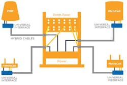
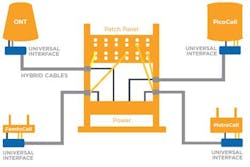
Let’s look at two approaches to this solution:Powered fiber A powered fiber cable combines single- or multi-mode fiber along with a copper power cable. The cable system includes a rack-mounted power and optical fiber termination point, the cable, and a remote termination node for each device that plugs into the cable. The system uses plug-in electrical connectors so the carrier needn’t have an electrician at the remote sites to install connections.
Figure 1: Powered fiber cable system components In a powered fiber system, each cable is capable of powering a 25W device at a distance of up to one kilometer, giving the system much farther reach than POE systems. An optional media converter allows the powered fiber cable system to be used for PoE if desired. The system incorporates DC/DC conversion technology to eliminate DC line powering calculations, and it features primary, secondary, and tertiary electrical protection for use in harsh outdoor environments as well as indoor venues.Power over Ethernet (PoE) Another approach is to use PoE. The PoE 802.3at standard can provide up to 25.5 W of power over distances of up to 100 meters on CAT 5 cable. To provide power for PoE, the Ethernet switch must have an additional power supply delivering typically 1480 W solely for PoE ports. One big advantage to PoE is that it supplies power and connectivity over one cable as long as the remote device is designed to accept power in that manner. IP phones and IP cameras are often set up for PoE. A disadvantage is that it’s an Ethernet cable standard, so it precludes using fiber, which is needed for high-bandwidth applications such as backhauling small cells. In addition, given the relatively limited reach of PoE, it is often not suitable for deployment in central offices or other serving offices where base station and controller equipment for small cell networks is located. Typically, the Ethernet switch that provides the power and connectivity is located in the same building or in a wiring closet near to the remote devices being powered.Carrier Ethernet 2.0 (CE 2.0) In addition to providing power with connectivity, service providers need a way to deliver Ethernet over their fiber infrastructure. The Metro Ethernet Forum’s Carrier Ethernet 2.0 (CE 2.0) standard enables service providers to transport Ethernet over fiber infrastructure. Since 2012, CE 2.0 has been having a significant impact on the market. CE 2.0 greatly expands from three services in CE 1.0 to eight services, two of each respectively in E-Line, E-LAN, E-Tree and E-Access (defined in MEF Standards MEF 6.1, 22.1, 33). Features of CE 2.0 include: • The industry's first standardized Multi-CoS with application-oriented CoS Performance Objectives, new metrics (MEF 6.1, 10.2, 20, 23.1) • Interconnect through the integrated delivery of MEF Service Attributes (MEF 10.2, 26.1, 33) allows ubiquitous deployment spanning multiple providers • Manageability, (MEF 7.1, 16, 17, 30, 31) plus additional specifications For service providers, CE 2.0 is a set of MEF CE 2.0 certified network elements that connect to transport Carrier Ethernet services for all users, locally and worldwide. Carrier Ethernet services are carried over physical Ethernet networks and other legacy transport technologies. Carrier Ethernet has enabled a transformation of the delivery of business services from legacy TDM, SONET and STM. In 2012, the total bandwidth of Ethernet services exceeded all other legacy technologies, worldwide, and has generated uninterrupted, double-digit service revenue growth since its inception (on track to exceed $100 billion in 2017).CE 2.0 and powered fiber

Carrier Ethernet 2.0 enables key applications from cloud services to mobile backhaul over all technologies using traditional or SDN approaches. On its face, CE 2.0 is a service delivery standard, and does not address the need for local power at the remote equipment site. For example, CE 2.0 has been used to backhaul traffic from small cells, but it does not generally provide power for those small cells.

However, when transported over powered fiber cable, the CE 2.0 protocol stands to provide the best of both worlds: it delivers carrier services with class of service, interconnect, and manageability, and would deliver power to remote locations, so that providing local power is no longer a problem.

RYAN CHAPPELL is global business development manager, optical cabling, at TE Connectivity. He began in the optics industry in 1994. Ryan has held various roles with multiple companies in research and development, engineering, marketing, and sales of optical cable, optical fiber, and other components of optical cable.

Sponsored Recommendations

Power up your system integration with Pulse Power - the game-changing power delivery system

May 10, 2023
Pulse Power is a novel power delivery system that allows System Integrators to safely provide significant power, over long distances, to remote equipment. It is a Class 4 power...

Network Monitoring- Why Tap Modules?

May 1, 2023
EDGE™ and EDGE8® tap modules enable passive optical tapping of the network while reducing downtime and link loss and increasing rack space utilization and density. Unlike other...

400G in the Data Center

Aug. 3, 2022
WHATS NEXT FOR THE DATA CENTER: 400G and Beyond

The Agile and Efficient Digital Building

May 9, 2023
This ebook explores how intelligent building solutions can help businesses improve network infrastructure management and optimize data center operations in enterprise buildings...