Structured cabling: the inside story
A look at the elements of structured cabling and the TIA/EIA-568B.1 standard.
The United States ANSI/TIA/EIA telecommunication standards lead the world in providing guidance and detail in the design of logically structured cabling systems. At the heart of these standards is the desire to provide a model for a cabling plant that will allow the running of a variety of applications in a frequently changing, multi-tenant environment for a period of 5 to 10 years.
Anixter Inc.'s (www.anixter.com) Technical Support Team, a part of Anixter's Levels Lab, often receives questions about current and future standards requirements. While the standards have been in publication since the early 1990s, there remains a large body of contractor/installers, many new to the field, who request clarification and guidance in understanding the principles of structured cabling. Since the early 1990s, Anixter has recommended structured cabling and has provided a LAN Cabling Workshop for end users and contractors on a not-for-profit basis.
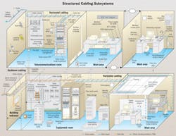
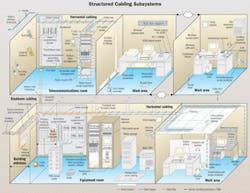
This article is summarized from portions of our frequently updated course. The drawing on page 42 was developed to assist customers, contractors, end users, and sales staff in the identification of common elements required in a structured cabling system.
A structured cabling system is divided into six conceptual subsystems: building entrance, equipment room, backbone, telecommunications room, and work area (as identified in the drawing).
Voice cabling
Outside plant cables enter at the building entrance for utilities. Any shielding or armor in the cable construction must be grounded with a shield bond connector and #6 ground wire that runs to the grounding busbar network. As soon as possible, and no more than 50 feet from building penetration, the flammable OSP cable is cut, stripped back, cleaned of any gel-fill, and terminated to building entrance protection (BEP) blocks, which shunt higher-than-normal voltages (over 300 V) to ground via the busbar network.
From the BEP, the pairs are punched down on telephone company 66 blocks (orange). These will route to an equipment room, which is the central location for the private branch exchange (PBX) and network electronics. At this point, secondary protection modules are often added to protect the PBX or other electronic device from excess voltage or current that could pass the primary BEP. Individual secondary protection modules are used to provide lower and more precise "clamping" voltages, usually in the 7.5- to 75-V range. Secondary protection can also be used to provide additional "sneak current" protection if the primary protector (BEP) does not have it.
The voice cables (trunks) are terminated onto the upper left-hand field (green) of the main crossconnect (MC). These cables cross-connect to the lower left-hand trunk field (purple), and pre-terminated 25-pair cables route the incoming lines to the PBX. Calls handled by the PBX are routed back to the center MC fields (purple, labeled "PBX") and cross-connect to the right column of the MC fields (white, labeled "riser" and blue, labeled "area"). Here they may follow backbone paths to telecommunications rooms or local horizontal paths to information outlets in individual work areas.
Category 3 is currently the minimum acceptable specification for voice cable. In the horizontal path, the illustration shows cable supported by ladder runway and a lightweight cable tray. You can also use J-hooks here. A consolidation point or multi-user telecommunications outlet assembly (represented as zone cabling here) may be used in this path. Along the backbone path, the cables are supported and protected along their vertical route, with firestop materials installed whenever cable penetrates the floor. The voice backbone cables are shown terminated at another crossconnect in the telecommunications room, from which they travel down horizontal paths to the work area. Voice crossconnects are commonly mounted on plywood backboards.
LAN data cabling
LAN data cabling follows a similar series of paths. Hubs or switches in the equipment and telecommunications rooms are connected via 62.5/125- or 50/125-µm multimode optical-fiber pairs. This fiber backbone may extend to other buildings in the complex. Communications from the work areas is routed down horizontal paths to the back of patch panels that interconnect to the switch via a patch cord. Category 5e is the minimum specification for the data runs to the work areas. The switch routes messages over the backbone or back down the horizontal to adjacent work areas. While 10Base-T networks still predominate nationally, leading facilities are installing 100/1000Base-T Ethernet switches. As illustrated, data crossconnects are usually rack- or cabinet-mounted. Vertical and horizontal cable management is provided to accommodate frequent adds, moves, and changes. Rack-mount surge suppressors and uninterruptible power supplies (UPS) are often recommended. A main UPS provides backup power to the PBX.
Telecommunications rooms (no longer called "closets") and dedicated equipment rooms are the result of the increasing complexity and integration of voice, data, paging, wireless LAN, broadband video, security, building automation, and Internet service provider requirements. New standards integrating these services are under development and nearing completion.
In the work area, additional surge suppressors and standby UPSs are shown providing power line protection or backup power to mission-critical workstations. Voice paging and wireless paging signage is indicated, as are common wireless LAN devices. Note that the last portion of the horizontal cable paths may route through walls, down vertical columns or power poles, through modular furniture, or through surface raceway. Poke-through and small floor access panels are also possible, where necessary.
Structuring for the future
The preceding overview of a properly designed structured cabling system is useful for visualization and general understanding of the elements and concepts that should be considered in any design. Properly installed, labeled, and recorded, such an infrastructure allows for cost-effective adds, moves, and changes. It also allows for the running of a variety of applications, today and tomorrow, in a multi-tenant environment.
Not like it used to be
The new TIA/EIA-568B.1 standard replaces the standards document TIA/EIA-568A dated October 6, 1995. Significant technical changes are:
- The TIA/EIA-568A standard has been reorganized into three technical standards: TIA/EIA-568B.1 addresses only cabling system requirements, TIA/EIA-568B.2 addresses copper components, and TIA/EIA-568B.3 addresses fiber components.
- Category 5 is no longer recognized, and has been replaced by Category 5e.
- Performance specifications are provided for Category 5e.
- Performance specifications are provided for 50-µm optical fiber and cables.
- Small form factor (SFF) optical fiber connector designs are allowed.
- The term "telecommunications closet" has been replaced with "telecommunications room."
- The "permanent link" has replaced the "basic link" as the test configuration.
Frank Dickman is an RCDD manager of technology for Anixter Inc. (www.anixter.com). He is the voting member for Anixter on behalf of customer interests at several standards development organizations.
null
New standards reference guide
The new TIA/EIA-568B.1 standard incorporates several previous interim documents, including TSB-67, TSB-95, and Addendum 1, 2, 3, 4, and 5. Anixter has published a standards reference guide designed to help consultants, contractors, installers, and end users. This booklet summarizes the recent revisions in the 568B standards and covers elements of the 569, 606, and 607 standards.

