Cleaning practices needed for testing optical-fiber LANs
With the use of Gigabit and 10-Gigabit optical-fiber links becoming more common in new optical-fiber LANs, installers have taken interest in new technology and techniques. They have found that, typically, there are three steps to a successful design and installation of a high-bit-rate optical-fiber backbone link in a LAN:
- Choose optical-fiber cable and hardware that meet the bandwidth and loss budget of the target application;
- Install all network hardware using proper tools and procedures;
- Certify that the link meets its design insertion loss limits.
But three of the most significant factors contributing to the quality and cost of an optical-fiber network are often overlooked—the quality and cleanliness of the test cords as well as the certification procedures used during the final testing of the cable plant.
Moreover, it is likely that many installers add an error of several tenths of a dB to their insertion loss measurements, and possibly damage the connectors on the links under test, if they don't regularly inspect and clean the connectors on the test jumpers being used. In fact, the success of any optical-fiber installation contract may depend not just on the cable bandwidth and the connector termination technique, but also remembering to bring a box of cleaning wipes to the job site.
Clean and inspect
Unfortunately, the typical practice of testing fiber at the job site rarely seems to include routine cleaning and inspection of the reference cords; that is, unless an obvious insertion loss problem develops during the test process. Often, after such an insertion loss problem has developed while testing, the reference cord may have already encountered physical damage. In many cases, the damage may not even be detectable when inspecting the connector end faces with a hand-held fiber microscope.
null
Throughout the fiber testing process, the reference cord connectors may pick up debris called "particulate" in the form of dust particles, or microscopic materials ground off from the mating adapter's alignment sleeve. All of these contaminants affect the final test outcome due to attenuation caused either from obstructing light in the fiber or from the air gap created between the two mating connectors.
The reference cord connectors can then transfer this debris from port to port, compounding the issue during repetitive tests and potentially threatening the quality of the installed connectors.
Inaccurate test results
During this process of particulate transference between adapters, debris can build up, creating several concerns. The first is that the test result of any given port adapter may not be accurate based on the amount of debris that was present in the adapter when the test was taken. Test results gathered could vary greatly when debris is introduced on the fiber since it can shift around on the connector face between tests.
null
null
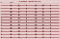
The table on page 30 illustrates the systematic test of a 24-port patch panel, without cleaning either the port being tested or the reference cable in between tests.
Although certain ports seem to test well, other ports have very high loss values. (Each one of the connectors being tested had been qualified with 400× inspection and a Norland NC3000 Interferometer to confirm polish quality.) This is because the reference cord connector picked up debris through the process of transference. Any technician who has ever tested fiber on a job site can attest to the fact that non-repeatable test results are typical whenever there is a lot of airborne contamination in an area where fiber panels are being tested.
The second concern created by transference is a bit more difficult to diagnose and is also more problematic in the long run—the quality or "end face geometry" of the reference cord connectors. The geometry is the measure of a connector's polish and finish, which can be altered on a microscopic scale every time the connector is mated. The situation is amplified whenever the connector is mated with debris on its end face. Debris can cause pitting, scratching, micro-fractures and fiber compression—all of which change the connector's ability to obtain an accurate, repeatable result. The damage can also cause a connector to permanently lose its original loss characteristics.
During testing, it's most likely that a field technician will remove the reference cord from the adapter port that is producing a high-loss result, clean the reference connector and re-insert the reference cord back into the port for a second test. This may result in a slightly lower test outcome on that particular port, in some cases; but by principle, it is unlikely that the debris was not entirely removed by this cleaning.
When two connectors are mated in an alignment adapter, both end faces contact each other, and any debris that is present on one connector will be shared between the two. When the technician removes the reference cord, it's probable that as much as 50% of any contamination present will remain on the mating connector still locked into the adapter.
null
Using port cleaning swabs to clean this connector that's still in the adapter is the easiest method to keep particulate from building up. Using canned air is not recommended, since many brands can leave fluid build-up or create a static charge that actually attracts airborne particles.
Many technicians are unaware of the debris on the mated (backplane) connector because they don't have the proper equipment to detect it. A portable video fiberscope probe is an important tool for inspecting these adapter ports. It lets the technician evaluate connector end faces that are mated into the adapter backplane, without having to remove them for inspection. Without the probe tool, the process is fairly awkward and includes removing the connector under test from the adapter backplane to manually inspect it with the hand-held scope.
Mating sleeve types
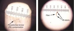
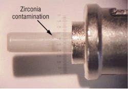
The next item of interest is the type of mating sleeves or adapters used in the patch panel. The two most common types of adapter sleeves are either phosphorous bronze (PB) split sleeves (typically used for multimode applications) or zirconia (ceramic) split sleeves (typically used for singlemode applications). For economy installations, sleeves can also be made out of polymers.
When choosing an adapter, it's important to consider the amount of contamination produced by the sleeve's material. Although they are less expensive, phosphorous bronze sleeves are known to contaminate connector end faces with metallic shavings. Zirconia-sleeved adapters are less likely to contaminate the connector end face with debris, but all split-sleeve alignment tubes are prone to collecting dust and particulate, regardless of sleeve type.
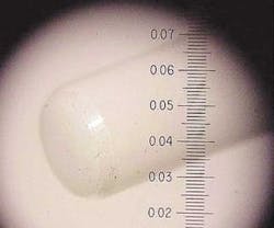
The photos above show alignment sleeve contamination produced by both phosphorous bronze and zirconia.
The geometry of the connector's polish can be altered on a microscopic scale every time the connector is mated. This damage can also cause a connector to permanently lose its original reference value because the geometry quality has been compromised. This damage is difficult (if not impossible) to diagnose with typical field inspection microscopes, since they only reveal a two-dimensional view of the connector end face.
null
With the use of an optical-fiber connector interferometer, the true end face quality of a connectors' polish can be illustrated in a three-dimensional model of the connector's end face. This device can measure the effects of zirconia-ferruled connectors and the damage created through cyclic mating over a period of time. The figure on page 29 illustrates this damage from mating connector pairs in phosphorous bronze-sleeved adapters. These reference cord connectors were measured for original quality (shown as Beginning Geometry) and then subjected to the number of matings listed, without cleaning between these matings.
The phosphorous bronze-sleeved adapters display images that reveal more axial compression damage to the fiber, and fiber deterioration due in part to increased levels of particulate and debris.
In certain circumstances, this damage can be so severe that the loss results of the reference cord are changed as much as several tenths of a dB. This damage can manifest itself on a single job, and cause cumulative damage to the reference cords over thousands of matings on dozens of different job sites.
Know your cords
It's important to develop a method for rotating test kit reference cords to alleviate this ongoing deterioration. In addition, when you purchase reference cords, they should be tested to ensure the best quality end-face geometry. Always select cords that are Telcordia-compliant, guaranteeing that the connector ends have been certified to stringent industry standards for polish quality—including fiber height, apex of polish and radius of curvature. These cords will serve as a "golden reference;" or, in other words, a known good cable with low loss and repeatable test attributes.
To maximize the life of cord sets, prepare a procedural test method—one that should guarantee that each test is with a clean connector and adapter, and with a clean, Telcordia-compliant reference cord.
Before each test, conduct a video fiberscope inspection of the port being tested, using a port-cleaning swab to clear any debris and confirming cleanliness of the reference cord connector. Following this procedure, you will rarely have a test that isn't repeatable and stable.
These cleaning processes will undoubtedly slow down the test acquisition, but they will also yield more accurate test results and less damage to both the customer's cable plant under test as well as your reference cords.
And after all, the test results submitted at the end of the job represent the benchmark that end users employ to measure the credibility of their optical-fiber installation contractor.
Craig Bowden is president of FiberNext LLC (www.fibernext.com). Chris Blair is director of marketing for Noyes Fiber Systems (www.aflfiber.com). Bowden can be reached at: [email protected]


