There are varying objectives in most storage area networks/network-attached storage and S/390 deployments, but a few things are always desirable: high availability and reliable data transmission.
Because network hardware must be physically interconnected with some type of cable transport, the performance metrics for these most basic objectives are influenced in large part by the cable infrastructure.
Structured optical-fiber distribution in the raised-floor environment is the solution to cabling disorganization. Some of the primary features and benefits that can be exploited through a modicum of planning and investment include:
- Significant reduction in number and volume of discreet cables under the raised floor. This allows for improved efficiencies in problem identification, troubleshooting and cable relocation efforts, improved airflow and cooling efficiency in densely populated areas, and simplification of management documentation.
- Efficient consolidation of physical hardware ports that are otherwise distributed throughout the data center facility. Allows for vastly improved manageability and control over the physical connectivity, facilitation of cable inventory standardization, and continuous data center growth.
- Reduced jumper cable lengths for above-floor management. Allows for much faster equipment moves, adds and changes, and risk abatement through minimizing the need to work under the raised floor.
- Ruggedization of permanent cabling for longer sub-floor spans. Allows for preservation of cable investment and risk reduction.
- Thorough and accurate documentation. Enables improved manageability, reduced downtime, and lower cost for upkeep, and ease of re-ordering and planning.
Precise cable pathways. Allow for improved environmentals, enhanced vendor control, and fire control and protection.
Minimizing the mess below
One of the key objectives for a structured cabling plan is to minimize the number and volume of discreet cables under the raised floor. Take, for example, an enclosure loaded with four McData ED-140M directors. At 132 ports each, this enclosure would have 528 discreet jumper cables coming and going to servers, storage or other devices distributed throughout the data center.
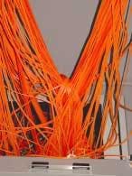
If the floor tiles immediately in front of or behind this enclosure are removed, one would often find a horribly tangled mass of orange cabling piled a foot or two off the cement. The weight of this pile is usually putting physical stress on many of the connections at the directors' ports.
Jumper assemblies are strong, but the most common cause for a "bad" cable is typically found in the connector. Long-term trouble can come when you focus cable tension right at the point where the cable is connectorized. It may function when you leave the installation site, but it may not function six months later. The situation becomes worse when more cables are added to the pile.
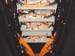
Contrast this methodology with one employing multi-fiber trunk cables. The same 528 ports could be much more efficiently cabled with eleven 48-channel trunk cables. This simple design change would eliminate 98% of the discreet physical cables exiting this director enclosure. Not only would the port-level stress be mitigated but it would be much less time consuming, for example, to locate, troubleshoot and/or move one of 11 cables as opposed to one of 528 cables.
Channel consolidation
A second key objective in the raised-floor environment is the efficient consolidation of physical hardware channels and ports that are otherwise distributed throughout the data center. Management of all of the physical hardware connections throughout the center can be simplified by exploiting a structured approach to cable transport.
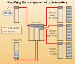
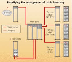
A typical structured cabling system includes distributed servers and FC directors on a data center's first floor, distributed servers on the second floor and distributed servers and storage on the third floor. Distributed servers and storage connect to remote distribution zone cabinets on their respective floors via jumper cables to the front side of each patch panel. Centralizing these remote zone cabinets lets the contractor standardize jumper lengths and simplify the management of cable inventory. From the rear side of the remote zone panels, trunk cables are run to the main distribution zone on the second floor. As a result, all of the distributed servers, storage and director ports can be managed at the patch panel ports in the main zone.
To illustrate the problems encountered in most data centers, assume that an end user has server farms on the first, second and third floors of a data center. (See figure, page xx.) The end user also has FC directors on the first floor and consolidated storage on the third floor. As the hardware configuration grows and changes, the end user will continue to add servers on all floors, directors on the first floor and storage on the third floor. Since this is network-attached storage (NAS), all of the storage connections as well as many or all of their server connections will come through the directors. If everything is direct-attached with jumper cables, the result will be an environment where long jumper cables criss-cross all over the data center, between and across floors.
Locating, moving, adding to or otherwise trying to manage these cables becomes exponentially more difficult as the environment grows. To further complicate matters, the discreet jumpers are stressed, entangled and put at risk for damage or compromise, endangering the data and information that they carry. With so many cables coming and going from all directions, it becomes nearly impossible to understand the totality of the environment so that it can be efficiently and effectively managed.
Instead of a haphazard, direct attach approach, the end user should introduce a system. Choose a centralized spot in the data center (main zone); extend all equipment channels and ports to this location for connection to distribution panels. From this "main zone," run multi-fiber trunk cables to strategically-located "remote" zone cabinets placed near the devices to be attached. These remote zones utilize short jumper cables with standardized lengths to complete the physical connection between the device interfaces and the main zone, where all of the other configuration connections are made.
null
To further this illustration, assume that the storage area network (SAN) was originally configured with 32 servers with dual host bus adapters (HBAs) and one 128-port FC director. The configuration manager decided that the installation was not large enough to merit a structured cabling system and so ran 64 jumper cables from the servers to the FC director and 64 jumper cables from the FC director to the storage and other input/output (I/O).
Addressing cable volume complexity
Assume that the business conditions require the addition of 32 new servers and an another FC director. Half of the existing server jumpers will need to be rerouted to allow HBA ports from each server to connect to both FC directors, creating independent, redundant paths. In this illustration, 32 of the existing server ports need to be disconnected and rerouted under the raised floor for connection to the new FC director.
After the existing jumpers have been moved, 64 additional jumper cables are installed under the raised floor to complete the project installation (32 from new servers to existing director and 32 from new servers to new director). In addition, half of the jumpers connecting the existing director to storage and I/O will likely be removed in favor of I/O connections from the new director. As additional servers, directors and I/O are added to the configuration, this job becomes exponentially more complicated, due to the multiplying cable volume under the raised floor.
In contrast, had the configuration planner started with a structured cabling system in the beginning, the server HBAs and FC director ports would have been connected with trunk cables to patch panels in a main zone area. All of the interconnections between server HBA, director port and storage port would have been completed with short jumper cables between patch panel ports within the main zone. When the acquisition occurred, the new equipment would have been attached to new panels in the main zone.
As a result, the reconfiguration would have been accomplished by moving short, above-the-floor jumpers between the patch panel ports, instead of moving long jumper cable connections under the raised floor. This would have been vastly easier to accomplish, and unlike the former jumper solution, it would not have required making any physical disconnections at the active production equipment. The cable management system has significantly reduced the time required for this planned outage.
Neat trick
By employing these simple steps, you'll have eliminated 98% of the discreet cables required by the hardware configuration while consolidating and centralizing all of the hardware channels/ports where they can be easily managed above the floor. You'll have eliminated the need to move existing cables under the raised floor during reconfiguration, and created an infrastructure where any of the servers or storage devices can be reached from a remote distribution cabinet with a standardized, 50-foot jumper cable. This makes hardware configuration a much more manageable proposition and allows the manager to inventory jumper cables of standard lengths to reach I/O from remote zone cabinets.
Precision pathways
By using main and remote fiber cabinets, you'll have reduced the number of cable destinations for all long/permanent runs, creating precise cable routing paths that will allow for the installation of a protective conveyance system under the floor for routing trunk cables.
Once the system has been properly tested and documented, a raised-floor fiber distribution system will have been created—one that works as a tool to better service the needs of the configuration, operations and technical support personnel.
Christopher Shoop is a sales engineer for Conexus Technologies, West Chester, OH. (www.conexus-technologies.com).
Technical considerations when designing a structured cabling plant
Several technical considerations must be addressed when designing a structured cabling plant:
- Cable and connector options;
- Loss budgeting;
- Light propagation, or continuity;,
- Mode; and,
- Cable jacket rating.
While any of the common connector types—ESCON, LC duplex, MTRJ, MTP and SC duplex—can be utilized for passive connections at the patch panel level, it is important to verify what connector type is native to the machines being interconnected. The MTP connector, for example, is a 12-fiber, six-channel connector that can be used to consolidate physical connections and accommodate faster push-pulls.
Loss budgeting was never really an issue in a mainframe environment because loss tolerances were so high (8.0 dB). Depending on the desired data transmission speeds, today's fibre channel standards may require that losses be limited to less than 2.0 dB. For this reason, it is important to identify the desired transmission speeds, channel/port architecture and the loss performance of the connectors and cable media over distance—then comparing these items to accepted industry standards and specific equipment performance specifications.
Quality of connection can vary substantially from one cable assembly house to another, so it is important to get written performance guarantees for both the cable assemblies and the optical-fiber links that have been designed. (The optical-fiber link includes all of the cables, connectors, couplers and passive connections between transceivers or HBAs.)
Maintaining the appropriate continuity or polarity in an optical-fiber link is also critical to system performance. In a duplex environment, there is a transmitter and a receiver. Signals launched from a transmitter must be received by a receiver. As a result, there is a twist in the optical-fiber link that must be maintained. Industry standards typically call for a twist in every cable assembly; however, some cable assembly houses provide cables with "straight-through" polarity. It is important to specify the need for crossed-cable polarity and to make sure that consistent cable construction is provided from multiple vendors.
Because of the connector orientation on opposite sides of a coupler, a twist also occurs at all passive couplers. The key is to remember that the total number of twists in an optical-fiber link needs to be an odd number, which ensures that the transmitted signal ends up at a receiver on the other side of the link.
Many of the equipment performance characteristics are based on specific media and core diameter, so it is important to review equipment performance specifications carefully and incorporate the appropriate fiber—singlemode or multimode.
Selection of cable jacket rating should be based on the local fire code. Plenum-rated cable has low smoke/low flame properties for use in plenum spaces mandated by many local fire marshals. Because plenum cable is more expensive and less pliable than its riser counterpart, it should not necessarily be selected by default.
The properly designed cable infrastructure is one that minimizes the number of discreet cables placed under the machine room floor, consolidates distributed equipment ports for above-the-floor management and troubleshooting, provides for simplified, modular growth, and adds layers of cable protection, labeling and documentation.
Some technical considerations cannot be ignored, but the art and the pay-off are in visualizing the future needs of the data center, and in designing a system that will facilitate the data center's future performance and growth demands.—CS
Raised floor manufacturers
The following manufacturers offer raised-floor systems for data centers and other networking environments. Visit the companies' Web sites for more detail on their product lines.
Flexspace
Seattle, WA
www.cablefloor.com
Maxcess Technologies
Summerville, SC
www.mtiaccessfloor.com
Multilink Broadband
Elyria, OH
www.multilinkbroadband.com
Tate Access Floors
Jessup, MD
www.tateaccess.com
If your company manufactures raised floors and would like to be included in future editorial coverage of this product line, please call Patrick McLaughlin, chief editor, at 603-891-9222.


