TIA data-center standard nearing completion
The TIA/EIA-942 standard will define new terms and address media selections, the center's physical environment, and equipment placement.
Significant changes in data-storage applications, data-storage equipment, and storage area networks (SANs) have altered the telecommunications infrastructure requirements for data centers and computer rooms.
Mainframes and their support peripherals are being supplanted by high-performance servers interconnected with gigabit-speed data links. The decentralization of computing resources from large mainframes to distributed server clusters has significantly impacted the infrastructure design for data centers and computer rooms. From an application perspective, many of the larger data centers are providing the physical environment for Internet Service Providers (ISPs) with Web-hosted Internet applications operating 24/7.
The requirements for an ISP data center can be significantly different from the requirements for a single enterprise. Although the design and operational requirements for a 24/7 fault-tolerant secure network infrastructure are best facilitated through an integrated design approach, that is not the case in practice. In many instances, the data centers and supporting facilities are often considered separately as an afterthought in the building-development process.
The TIA/EIA-942 standard
With an expected publication in early 2005, the Telecommunications Industry Association (TIA; www.tiaonline.org) is nearing completion of TIA/EIA-942—the Telecommunications Infrastructure Standard for Data Centers. The standard's primary purpose is to provide a comprehensive understanding of data center design, including the facility planning, cabling system, and network design.
Targeted at bridging the information gap between a data center's design and construction phases, the standard takes a multidisciplinary approach to the document content and structure, facilitating coordination and cooperation among the architect, building engineer, and telecommunications engineer.
The standard provides design requirements and informational annexes that detail recognized "best practices." Design requirements include cabling as well as pathways and spaces. Annexes provide information on a wide variety of subjects related to the data center design, including:
- Data center sizing and site selection;
- Data center cabling infrastructure administration;
- Architectural and structural considerations;
- Security and fire protection;
- Electrical, grounding, and mechanical systems;
- Application distances;
- Access-provider coordination and demarcation.
In addition, the standard provides specifications corresponding to industry-standard data center reliability tiers, where Tier 1 has no redundancy and Tier 4 provides the highest degree of fault tolerance. The architecture, security, structural, electrical, grounding, mechanical, and fire protection guidelines are organized into four tiers.
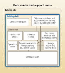
Data center spaces
The standard defines a data center as a building or portion of a building whose primary function is to house a computer room and its support areas. The computer room is that portion of the data center whose primary function is to house the data processing equipment.
The standard provides requirements for the computer rooms and entrance rooms in data centers, including: ceiling height (8.5 feet), floor/wall ceiling treatment, lighting, floor loading (150 lbs./sq. ft. minimum, 250 lbs./sq. ft. recommended), heating/ventilation/air conditioning (HVAC), temperature (68° to 77° F), relative humidity (40% to 55%), power, grounding, and fire protection.
Data center telecommunications spaces include:
- Entrance room;
- Main distribution area (MDA);
- Horizontal distribution area (HDA);
- Zone distribution area (ZDA);
- Equipment distribution area (EDA).
The entrance room is the space where the data center structured cabling system interfaces with campus cabling systems and the access-provider cabling systems. This space may be either inside or outside the computer room. If it is inside, it may be combined with the MDA.
A data center may have multiple entrance rooms for redundancy or to avoid exceeding maximum circuit length restrictions. For example, T-1 circuit lengths typically are restricted to a maximum of 655 feet while T-3 circuit lengths typically are restricted to 450 feet. But cable type and intermediate cross-connections can reduce these distances significantly. The standard provides guidance regarding maximum circuit lengths in data centers.
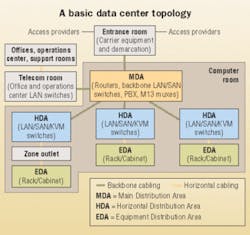
The MDA includes the main cross-connect, which is the central point of distribution for the data center structured cabling system, and may include horizontal cross-connects for horizontal cabling to equipment areas served directly from the MDA. The MDA often houses core routers and switches for the data center LAN and SAN infrastructure. The standard specifies that data centers have at least one MDA and may have a secondary distribution area for redundancy.
The HDA includes a horizontal cross-connect—the distribution point for horizontal cabling to EDAs. The HDA typically houses LAN, SAN, and KVM switches for the equipment in the EDAs.
An optional interconnection point within the horizontal cabling is called a zone distribution area, or ZDA. This area is located between the horizontal and equipment distribution areas to allow frequent reconfiguration and flexibility. Horizontal cabling in the ZDA is terminated in a zone outlet or consolidation point. Where the ZDA supports a zone outlet, patch cables are used to connect equipment to the outlet. Zone outlets are useful for floor-standing systems or for systems where it is not possible or convenient to install a patch panel inside the system cabinet. It is recommended that the ZDA not contain a cross-connect or active equipment (except equipment to provide inline DC power).
The EDA is the space allocated for end equipment, including computers and telecommunications equipment. Horizontal cabling is terminated in the EDA on outlets, which are typically located on patch panels mounted in an equipment cabinet or rack. The standard recognizes that an EDA may include equipment that are directly cabled to each other—for example, switches and blade servers or severs and peripherals.
A data center may also include a telecommunications room located outside the computer room to support horizontal cabling to spaces such as the support staff offices, operations center, electrical rooms, mechanical rooms, loading dock, and other data center spaces outside the computer room.
A typical data center includes one or two entrance rooms, one or more telecom rooms, one MDA, and several HDAs.
The data center cabling system includes the following elements:
- Horizontal cabling;
- Backbone cabling;
- Entrance cross-connect in the entrance room or MDA (if the entrance room is consolidated into the MDA);
- Main cross-connect in the MDA;
- Horizontal cross-conect in the HDA, MDA or telecommunications room;
- Zone outlet or consolidation point in the ZDA;
- Outlet in the EDA.
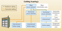
Horizontal cabling is the portion of the telecommunications cabling system that extends from the outlet in the EDA or zone outlet in the ZDA to the horizontal cross-connect in either the HDA or MDA. Horizontal cabling may include an optional consolidation point in the ZDA. Backbone cabling provides connections between the MDA, HDAs, telecom rooms, and entrance rooms in the data center cabling system.
Cabling topology
A star topology is used in the data center's horizontal and backbone cabling. Horizontal cables are connected to a horizontal cross-connect in either a HDA or MDA; however, for redundancy, different outlets within an EDA or ZDA may have horizontal cabling to different horizontal cross-connects.
Backbone cabling uses a hierarchical star topology where each horizontal cross-connect in the HDA is cabled directly to a main cross-connect in the MDA. Only one hierarchical level of cross-connect in the backbone cabling is allowed. There are no intermediate cross-connects within the data center cabling architecture.
The architecture permits the addition of a secondary distribution area for redundancy. In this case, all horizontal cross-connects in HDAs have backbone cabling to the MDA as well as to the secondary distribution area.
The architecture also permits optional direct cabling between horizontal distribution areas for non-star configurations, redundancy, and to support applications where generic cabling distances may exceed the application distances.To avoid exceeding maximum circuit-distance restrictions, direct cabling between a secondary entrance room and HDAs is also allowed.
Cabling media
The standard recognizes multiple media types to support a wide variety of applications, but it recommends that the highest capacity cabling media be used for new installations to maximize the flexibility and useful life of the data center's cabling infrastructure.
The recognized media are:
- 100-Ω twisted-pair cable (ANSI/TIA/EIA-568-B.2); Category 6 is recommended (ANSI/TIA/EIA-568-B.2-1);
- Multimode optical-fiber cable—either 62.5/125-µm or 50/125-µm (ANSI/TIA/EIA-568-B.3), 50/125-µm 850-nm laser-optimized multimode fiber is recommended (ANSI/TIA-568-16-B.3-1);
- Singlemode optical-fiber cable (ANSI/TIA/EIA-568-B.3);
- 75-Ω (734 and 735 type) coaxial cable (Telcordia Technologies GR-139-CORE) and coaxial connectors (ANSI T1.404). These cables and connectors are recommended to support T-3, E-1, and E-3 circuits.
Data center pathways
The standard recognizes a variety of cabling pathways, including the access floor (raised floor) systems and overhead cable tray systems (typically used in data centers).
Access floor systems are recommended in centers that need to support high-power densities or in data centers that support large computer systems (such as mainframes) that are designed to be cabled from below. Telecommunications cabling under access floors are recommended to be placed in cable trays, preferably those that do not block airflow and that have no sharp edges.
The standard recommends that overhead cable trays be suspended from the ceiling rather than attached to the top of cabinets or racks. Suspended cable trays provide more flexibility for supporting cabinets and racks of various heights.
The standard also recommends placing lighting fixtures and sprinkler heads in aisles between rows of equipment, not directly above them. A section on racks and cabinets provides illustration and details on their suggested floor and equipment placement within the racks and cabinets.
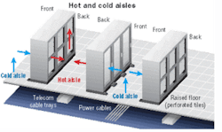
In addition, the standard recommends arranging equipment rows in an alternating pattern, with cabinets/racks front-facing each other to create hot and cold aisles. Cold aisles are in front of racks and cabinets; if there is a raised floor, power distribution cables are typically run here on the slab. Perforated tiles should be placed in cold aisles. Hot aisles are at the rear of racks and cabinets, where cable trays for the telecommunications cabling are typically placed.
Equipment should be placed in cabinets and racks with "cold" air intake at the front of the cabinet or rack, and "hot" air exhaust out the back. Reversing equipment in the rack will disrupt the proper functioning of hot and cold aisles. Equipment that uses the front-to-rear cooling scheme should be used so as not to disrupt the functioning of hot and cold aisles.
Cabinets need adequate ventilation to ensure proper equipment cooling. If the cabinets have no fans to enhance the functioning of the hot and cold aisles, the cabinet doors should be at least 50% open space.
Providing adequate clearance for the installation of equipment in the front of cabinets/racks enables efficient equipment placement and cabling. Front clearance should be 4 ft. (3 ft. minimum). Clearance behind cabinets and racks should be 3 ft. (2 ft. minimum).
Rack and cabinet placement should permit tiles at the front and rear to be lifted. Cabinets should be aligned with either the front or rear edge along the edge of the floor tile. Racks should be installed toward the center of the floor tile to ensure that the threaded rods that secure the racks to the slab will not penetrate a raised floor stringer.
Floor tile cuts under cabinets and racks should be no larger than necessary to minimize air-pressure loss.
To minimize longitudinal coupling between power cables and twisted-pair cables, the standard specifies the required separation between twisted-pair and power cables. The standard provides a table of recommended separation distances based on number of circuits, electric circuit type, and power cable shielding.
The TIA/EIA-942 standard addresses an industry-recognized need for infrastructure requirements that can be applied to any data center, independent of size or usage, including small to large single-tenant enterprise data centers and small to large scale multi-tenant Internet hosting data centers.
Chris DiMinico and Jonathan Jew are co-chairs of the TIA TR-42.1.1 working group responsible for developing the TIA/EIA-942 standard. Jew is president of J&M Consultants. He can be reached at: [email protected]. DiMinico is president of MC Communications. He can be reached at: [email protected]. Both authors are members of the recently initiated BICSI committee developing a data center standard that will address best practices and implementation, complementing TIA/EIA-942.

