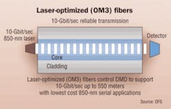
Also called OM3 fiber, laser-optimized fiber is the highest-capacity medium for short-wave 10-Gbit optical transmission.
As transmission speeds over optical-fiber networks in the enterprise increase to 1 and even 10 Gbits/sec and beyond, a relatively new term, “laser-optimized fiber,” has crept into the industry’s vocabulary.
What is laser-optimized fiber? What do you need to know about it? And what exactly does the term “laser-optimized” mean? Understanding the answers to these questions will help you prepare for the latest wave in optical communications for enterprise networks.
Evolution of transmission speeds
Older, legacy optical-fiber systems used in premises applications, such as Token Ring, Ethernet, Fiber Distributed Data Interface (FDDI), and Asynchronous Transfer Mode (ATM), operated at relatively slow speeds, in the range of 4 to 155 Mbits/sec. These systems used inexpensive light sources called light-emitting diodes (LEDs), which were perfectly adequate for slower speeds.
Multimode fibers used in these systems were rated to certain minimum bandwidths, typically 160 MHz·km over 62.5/125-µm fiber at 850 nanometers (nm); 500 MHz·km over 50/125-µm fiber at 850 nm; and 500 MHz·km over both products at 1300 nm. These fibers were tested for bandwidth using an overfilled launch (OFL) test method, which accurately replicated real-life performance with an LED.
But as the demand for bandwidth and higher throughput increased, especially in building and campus backbones, LEDs could not keep pace. With a maximum modulation rate of 622 Mbits/sec, LEDs would not support the 1-Gbit/sec and greater transmission rates required. You could make use of traditional Fabry-Perot or distributed-feedback lasers, typically used with singlemode fiber, but these types of lasers are expensive due to the higher performance characteristics required for long-distance transmission.
In response, the industry developed a high-speed laser light source called a vertical cavity surface-emitting laser (VCSEL). This technology is inexpensive compared to Fabry-Perot and distributed-feedback lasers, and is well suited for lower-cost, 850-nm multimode transmission systems, allowing for data rates of 1 and 10 Gbits/sec in the enterprise. With the emergence of VCSELs, however, multimode fiber had to be “optimized” for operation with lasers.
Fiber vs. performance
Why optimize for lasers? VCSELs provide higher power, narrower spectral width, smaller spot size, and faster data rates than LEDs. All of these advantages add up to a significant performance boost, assuming, of course, the fiber itself does not hinder performance. To understand why this could occur, we need to know the differences between VCSELs and LEDs, and how they transmit signals along a multimode fiber.
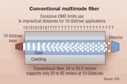
All LEDs produce a smooth, uniform output that consistently fills the entire fiber core and excites the many hundreds of modes in the fiber. The fiber’s bandwidth is determined by the aggregate performance of all the modes in the fiber. If a few modes lag behind or get ahead due to modal dispersion, they have little impact on bandwidth because many other modes are carrying the bulk of the signal.
A VCSEL’s energy output, however, is smaller and more concentrated than that of an LED. As a result, VCSELs do not excite all the modes in a multimode fiber, but rather a restricted set of modes. The fiber’s bandwidth is dictated by this restricted set, and any modes that lag or get ahead have a much greater influence on bandwidth.
Typically, a VCSEL’s power would be concentrated in the center of the fiber, where older fibers were prone to defects or variations in the refractive index profile (the critical light-guiding property in the core of the fiber), resulting in poor signal transmission. That is why some fibers may actually perform poorly with a VCSEL compared to performance with an LED.
To complicate matters, a VCSEL’s power profile is non-uniform and fluctuates constantly. It changes sharply across its face, varies from VCSEL to VCSEL, and varies with temperature and vibration fluctuations. Consequently, individual VCSELs will excite different modes in a given fiber at any given time. And because different modes carry varying amounts of power, the fiber’s bandwidth can vary in an unpredictable manner.
New light source, new fiber
With the advent of VCSELs, it became apparent that the traditional multimode fiber deployed for LED systems did not take full advantage of VCSELs’ performance benefits.
To fully capitalize on the benefits that VCSELs offered, fiber manufacturers developed laser-optimized multimode fiber (LOMMF), which is specifically designed, fabricated, and tested for efficient and reliable use with VCSELs.
LOMMF should have a well-designed and carefully controlled refractive index profile to ensure optimum light transmission with a VCSEL. Precise control of the refractive index profile minimizes modal dispersion, also known as differential mode delay (DMD). This ensures that all modes, or light paths, in the fiber arrive at the receiver at about the same time, minimizing pulse spreading and, therefore, maximizing bandwidth. A good refractive index profile is best achieved through DMD testing.
VCSELs and LOMMF provide tremendous flexibility and cost efficiency in “freeing up” bandwidth bottlenecks in the enterprise, today and well into the future. LOMMF is completely compatible with LEDs and other optical-fiber applications (there are no special connectors or termination techniques required, and no effect on attenuation) LOMMF can be installed now and used at slower data rates until the need arises to increase network speed to 1 or 10 Gbits/sec. At that point, you only need to upgrade the optics modules to VCSEL-based transceivers. There is no need to pull new cable.
It is important to note, however, that not all laser-optimized fiber is 10-Gbit/sec capable. If 10-Gbit/sec capacity is in your future, you must make sure that the LOMMF you’re installing now is also 10-Gbit/sec-capable.
Originally developed for 1 Gigabit
The first laser-optimized fibers, introduced to the market in the mid-1990s, were designed for 1-Gbit/sec applications. Available in both 62.5/125-µm and 50/125-µm designs, these fibers extended the reach capability of 1-Gbit/sec systems beyond what the industry standards stated.
For instance, OFS’ 1-Gbit/sec laser-optimized 62.5-µm fiber can go 300 meters in a cost-effective, 1-Gbit/sec 850-nm 1000Base-SX system. 50/125 fiber offers greater performance, with a reach of 600 meters or more. These 1-Gbit/sec LOMMFs, coupled with 850-nm VCSELs, allow for the lowest system cost for building backbones and short- to medium-length campus backbones.
As attention turned to 10-Gbit/sec data rates, existing LOMMF designed for 1-Gbit/sec speeds did not provide the support needed for 300-meter backbone distances. Laser-optimized 62.5/125 fibers were limited to about 35 meters of 10-Gbit/sec transmission, and laser-optimized 50/125 fibers to about 90 meters.
Further refinement of the fiber’s refractive index profile was necessary to achieve 10-Gbit/sec data rates on multimode fiber to distances of 300 meters and beyond. Fortunately, advancements in DMD testing enabled the necessary improvements to the fiber-manufacturing process that would produce fiber with accurate, defect-free refractive index profiles.
During this development process, it became apparent that 62.5/125 fiber would not be capable of meeting the high performance demand for 10-Gbit/sec capability. 62.5/125 fiber has inherently lower bandwidth than 50/125 fiber, because its larger core carries many more modes. And more modes mean more modal dispersion and less bandwidth. As such, LOMMF for 10-Gbit/sec applications is only available with 50-/125-µm fiber.
In 1999, OFS introduced LaserWave 300, its first 50-µm laser-optimized fiber to support 10-Gbit/sec speeds up to 300 meters. LaserWave has a DMD-controlled core and exceeds 2,000 MHz·km effective modal bandwidth, or “laser bandwidth,” at 850 nm.
It is significant to note that these fibers are referred to in the TIA-568 standard as “laser-optimized 50-µm multimode fiber,” and in the ISO 11801 2nd Edition standards as OM3. (We at OFS encourage the use of the term OM3 because it is simple and does not leave room for confusion between this fiber and the 1-Gbit/sec laser-optimized fibers.)
OM3 fibers can be installed today and used with slower, LED-based systems. When 1-Gbit/sec capability is needed, the optical modules can be replaced and the same fibers will support 1-Gbit/sec transmission up to 1,000 meters or more.
Finally, on the same fiber, the system can be upgraded to 10-Gbits/sec by again “swapping out” the optical modules. At each step, the advantages of lower-cost 850-nm VCSEL technology can be realized.
With an eye to the future, these fibers will even support 40 Gbits/sec, anticipated to be the next Ethernet speed specified by the IEEE. Coarse wavelength division multiplexing (CWDM) will allow for this ultimate upgrade path by transmitting four different wavelengths at 10-Gbits/sec each. Reach at 40-Gbits/sec will be at least the same as today’s 10-Gbit/sec reach.
Measurements for optimizing fiber
Because LEDs have a uniform and consistent power profile that excites all the modes in a multimode fiber, the traditional OFL method of bandwidth measurement accurately predicts fiber bandwidth for LED applications. But because VCSELs only excite some of the fiber’s modes, and in a varying manner, the OFL bandwidth measurement cannot predict what the fiber’s bandwidth would be if the fiber were to be used in a VCSEL application.
In an attempt to overcome this uncertainty, a restricted-mode launch (RML) method of measuring bandwidth was developed. This measurement technique is the same as OFL, but as the name suggests, a restricted or smaller launch is used to light only some of the fiber’s modes.
This restricted launch is intended to replicate a VCSEL, but test results can vary depending on exactly how the light source is coupled with the fiber. In other words, the actual bandwidth achieved in an installed system may differ from the RML tested bandwidth. (For these reasons, it is OFS’ position that RML simply is not a reliable predictor of a fiber’s bandwidth.)
By now, it should be clear why fiber manufacturers developed laser-optimized fiber, and why DMD testing is so important. The refractive index has to be well designed and controlled to ensure that all modes exhibit minimal DMD and all arrive at the other end of the fiber at the same time. No matter which modes in the fiber are actually guiding the light, those modes will have minimal DMD and provide high bandwidth.
DMD testing provides such a clear picture of how individual mode groups carry light down the fiber, and which mode groups are causing DMD, that the standards require fiber to be DMD-tested to ensure adequate bandwidth to the rated distances for 10-Gbits/sec applications.
DMD testing, which was pioneered by Bell Labs and advanced by OFS, involves transmitting short-duration, high-powered laser pulses in small steps across the entire core of the fiber. Each pulse excites only a few modes at each step, and the individual pulse shapes and arrival times are captured at the other end of the fiber.
The DMD of the fiber is the difference between the earliest and latest arrival times of all pulses at all steps.
Powerful process tool
From this information, adjustments can be made to the fiber-manufacturing process to produce low-DMD (and, therefore, high-bandwidth) fiber.
With a highly advanced process for making fiber, DMD testing serves as a powerful process tool to maintain a precise refractive index profile; so much so that some fiber manufacturers are able to specify tighter DMD in certain regions of the fiber, such as its center.
TONY IRUJO is the customer technical support manager for optical fiber at OFS (www.ofsoptics.com), the former optical-fiber solutions division of Lucent Technologies.


