Fusion-splicing the FTTP network: what, where, and why
Where and when it makes sense to fusion splice vs. connectorize in key areas of the network.
Service providers today are deploying fiber-to-the-premises (FTTP) networks en masse as residential and business customers demand increasingly more bandwidth for taking advantage of the latest voice, data, and video technologies. It’s no great secret that the network solutions that will gain the attention of these providers will be those that offer the most flexibility, scalability, and interoperability-always at the lowest possible first-in and operational costs.
A key consideration in planning the network, from the central office (CO) to the optical network unit (ONU) on the side of each customer’s building, will be when to connect the optical cables using fusion splicing techniques and when it makes more sense to connectorize. Each approach has benefits at certain points in the architecture, and a careful examination of where and when to use each method can save costs during the build-out as well as through years of network operation.
Splice: the early option
Splicing in the outside plant (OSP) portion of any network has been the primary means of permanently connecting fiber since the 1980s. Fusion splicing involves using localized heat to melt or fuse the ends of two optical fibers together. Initially, this process used nichrome wire as the heating element to fuse fibers together.
New fusion-splicing techniques have replaced nichrome wire with carbon dioxide lasers, electric arcs, or gas flames to heat the fiber ends and fuse them together. The small size of the fusion splice and the development of automated fusion-splicing equipment have made electric arc fusion one of the most popular splicing techniques in commercial applications.
For high fiber-count applications, the process of mass fusion splicing has evolved to enable technicians to splice multiple fibers at once, typically in a ribbon configuration. Currently, some splicers on the market splice up to 24 fibers simultaneously.
When network visionaries first began looking at deploying FTTP infrastructures more than 10 years ago, the focus was on an all-spliced network. Every junction point in the fiber network, from the CO to the subscriber, was spliced together. At that time, the primary justification was the cost and concern over reliability of optical connectors in the OSP environment.
But vast improvements made in optical-fiber connectors in recent years have improved their performance in more austere conditions. Higher performance standards and manufacturing improvements have enabled many of today’s connectors to exhibit lower insertion and return loss characteristics. In fact, some connectors have successfully completed tests under extreme temperature variations ranging from -43° to 137° F.
Since environmental conditions can be endured reliably by either splices or connectors in the OSP, network architects are free to examine other conditions that would provide benefits of one method over the other.
Sensible connectorization
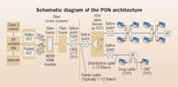
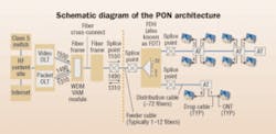
The general OSP architecture of an FTTP network that takes fiber directly to each home consists of feeder cables routing to a fiber distribution terminal (FDT) where optical splitters are housed. From the FDT, a distribution cable runs to the fiber service terminal (FST) where the drop cables will tie in. From the FST, each drop cable is routed to an optical network termination (ONT) attached to each subscriber’s home.
Throughout this network, there are numerous locations where fibers must be joined together, either by fusion splicing or through the use of connectors. At each of these points, it must be determined whether it makes more sense to use connectors or splices, based primarily on whether technicians will require regular access for testing, service turn-up or network reconfiguration.
Having easy test access at critical points in the network will save on future operational expenses. Typically, fault isolation in a fiber network involves connecting an optical time domain reflectometer (OTDR) to determine a fault location.
Two key challenges are posed to technicians assigned to this task:
• OTDR traces are difficult to decipher once the trace hits the 1×32 splitter in the FDT;
• Accessing the fiber without taking up to 32 subscribers out of service when only one has a problem.
Connectorizing each splitter output as a centralized demarcation box provides technicians with one access point for testing any fiber for multiple homes. A splice, on the other hand, would require a specialized splice technician to break into the appropriate splice between the splitter output and the distribution cable to connect an OTDR. The technician would then splice into the OTDR to run the trace and locate the problem. Once the trace is completed, the fibers must be re-spliced-an overall time-consuming and costly process.
Connectors should also be considered at the network junctures responsible for service turn-up-basically, at the FDT and FST. This is particularly important in applications where take rates may be significantly less than 100%. Splicing could make sense here if the take rate was nearly 100%, but consideration should also be given to customer churn and the adoption of new and future service offerings.
The basic rule of thumb is that wherever there is an ongoing requirement in the network for testing, troubleshooting, service turn-up, reconfigurations, or any other operation that requires continual access to the fibers, connectors make the most sense. Conversely, any time there is a need to lower loss budgets and maximize fiber reach, fusion splicing might be the necessary option.
Distribution vs. drops
Although many network architects agree that hardened connectors are optimal for the drop side of the service terminal, there are still three primary choices:
• Splicing both ends;
• Using preconnectorized drop cables;
• Using cables with one end preconnectorized and splicing the other end.
Splicing both ends will usually result in more capital and operating expense, particularly when considering future access requirements and the additional costs of using higher-trained personnel.
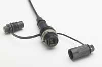
Preconnectorized drop cables provide greater flexibility, easier access, and can be installed by any technician. These cables are available at specific lengths and easily install between the service terminal and the home; simply clean the connector faces at each end and plug them in.
Of course, this requires service providers to maintain an inventory of preconnectorized drop cables for multiple applications. In addition, use of connectors traditionally results in higher loss budgets. Good storage-management techniques for slack are also necessary. Cost models for some vendors, however, have still shown lower overall installed costs using preconnectorized drop cables.
Using a drop cable that is preconnectorized on one end may be another alternative for some network architectures. A typical scenario would be to use the connector end to avoid making an aerial splice and offering a simpler slack-management solution by splicing at the ONU to a factory pigtail.
On the distribution side, however, fiber density is the key factor. In most cases, loose-tube fiber cable is being replaced by new ribbon cables that boast up to 864 fibers vs. the maximum 288 offered by loose-tube configurations. With ribbon, material costs also decrease since less plastic is involved and fewer strength members are required.
But perhaps the biggest benefit offered by ribbon is the ability to “mass”-fusion splice as compared to one-by-one splicing. So, for termination in areas of the FTTP network that require high fiber volumes, ribbon and mass fusion splicing are significant cost savers.
Further, ribbon cables are thermally efficient in OSP applications, minimally affected by temperature changes. Having all the cables in a central tube allows ample room for the fibers to move around as the sub-unit materials expand and contract.
What works best, and when?
As with the drop-cable portion of the network, connectorized ribbon cables at the distribution portion of the passive optical network (PON) are a sensible choice wherever access is required for testing or troubleshooting. But with the same criteria applied, if access is not required, mass fusion splicing is the more cost-effective method.
In terms of restoration following a major event, such as a cut cable, splicing is still the best method for reconnecting two or more fibers back together anywhere in the network.
The bottom line is that neither fusion splicing nor connectors are the right choice in every circumstance. But one is usually preferable over the other at certain points within the FTTP architecture. Determining when to splice and when to use connectors anytime fibers are joined is a matter of knowing what makes the most sense-now, and later in the life of the network.
Saving money during the deployment phase will not always produce savings in the operational phase, and vice versa. A little common sense, however, will go a long way in building the most flexible, reliable, and reconfigurable FTTP network.
TREVOR SMITH is senior product manager for OmniReach FTTX infrastructure solutions at ADC (www.adc.com). GARY BISHOP is director of product management at Sumitomo Electric Lightwave (www.sumitomoelectric.com).


