Fiber termination's most critical step: Polishing to perfection
How proper optical-fiber polishing techniques can improve network performance.

No matter how you splice it, a networking system is only as good as its weakest link. Chances are the weakest link in an optical-fiber system is a connector. If your network fails due to poor connector termination, the cost to find the problem and rework it can become significant.
With today’s increasing bandwidths demanding lower loss budgets, it is essential that fiber terminations do not impact the system’s performance. Well designed connectors, good termination practices, and installer skill become invaluable.
Many installers fear connectorizing optical-fiber cable, mainly due to the delicate techniques of polishing and lapping. Additionally, since the optical connector is a high-precision device with tolerances on the order of microns, it is crucial that the fiber not only be formed perfectly to align with a mating connector, but that it be free of any dust or dirt. Failing to do so can cause high insertion loss and high reflection, and can contaminate the equipment to which the connectors and patch cords will be connected.
Polishing the fiber is the last and most critical step in the connectorization process. Polishing finalizes the connector endface and cleans the surface, which has a direct impact on such optical performance parameters as insertion loss, return loss, and bit-error-rate for overall network performance. Reliable polishing processes rely on proper training and a well-equipped termination toolkit.
Time versus money
Several connectivity options are available, including patch cords (preconnectorized or preterminated cables), field connectorization, and one-end termination pigtails that require fusion splicing. Each method and its success depend on the connector termination process and installer expertise.
Preterminated cables, patch cords, or connectorized interconnect assemblies eliminate time-consuming field-termination processes and provide a factory-tested and certified endface, but can also have downfalls. Prepolished connectorized fibers can cost much more than epoxy-style field-polish connectors, and need to be precisely measured. If they are too short, you will have to install a replacement. If they are too long, you will have outlaid additional expense and still have to deal with installation issues associated with managing the extra cable length.

Epoxy/polish connectors, in which fiber is glued to the connector with heat-cured epoxy, provide a reliable connection with losses less than 0.5 dB per mated pair, but can be time-consuming because they need to set or “cure.” Anaerobic adhesive is a quick-setting adhesive that is rapidly replacing epoxy because it provides a simple installation process that does not require power. Additionally, anaerobic adhesive connectors will typically have less than a 0.3 dB insertion loss per mated pair, which is better than the TIA/EIA-568-B.3 standard-specified maximum of 0.75 dB per mated pair.
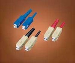
Connectors themselves vary greatly in design and style. TIA/EIA-604 outlines intermateability specifications, known as FOCIS (Fiber Optic Connector Intermateability Standard) documents. These specifications ensure that connectors by varying manufacturers are intermateable with those of other manufacturers. The FOCIS documents include specifics for the most widely used connectors, including SC, LC, FJ, MPO, ST, FC, and MT-RJ.
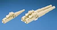
In the premises market, the SC, LC, FJ, and ST are the most predominant for both singlemode and multimode field installations. The SC offers low cost, simplicity, and durability, as well as accurate alignment with its ceramic ferrule and “push-pull” connection. The LC, designed for high density applications, features a small, 1.25-mm ferrule (half the size of its predecessors), which requires a more-precise polishing operation. Although the method for attaching optical-fiber connectors to optical fibers varies among connector types, the basic steps of termination and polishing are common.
Tools of the trade
Automated polishing equipment can provide higher first-pass yields and a more consistent product quality, but manual polishing techniques are common field practices for some connectivity types. Controlling the procedures in the field through emulating automated lab procedures or an assembly house will provide comparably high yields.
Most field connector manufacturers offer field termination kits and extensive training. Intermateability standards, such as TIA/EIA-604-3 for SC connectors, define tolerances and geometry of all mating parameters.
It would be ideal if connector termination kits would work across the board, but often, they do not because of different tooling and variances in consumable items. A kit from one manufacturer may not be capable of terminating another manufacturer’s connector, even though they are the same-style connector. So, you should be equipped with the appropriate toolkit, current editions of the manufacturers’ termination instructions, and the training to achieve the desired quality and performance levels.
The field termination kit should include distilled water (as a lubricant and flushing agent between each polishing process), anaerobic adhesive (to bond the fiber inside the ferrule), a cleaving tool (to cut off the fiber to the desired height above the ferrule), a portable microscope (200× minimum), and a polishing kit that includes a polishing puck, pads, and an assortment of films.
Become familiar with the many different materials available within these kits. Polishing pucks, which hold the connector in place during the polishing procedure, are made from high-abrasion resistant metal or plastic. Manufacturers, such as Panduit, offer a precision, case-hardened puck with tolerances for the ferrule to fit easily in the puck and allow free rotation. Polishing pads come in different materials, such as rubber or hard plastic, based on the manufacturer’s recommendation.
True grit
The most important element in a polishing kit is the polishing and lapping film, which consist of materials with abrasive particulate on a Mylar substrate in different grit sizes. The rate of fiber erosion within each polishing step is dictated by the film’s defined grade and erosion rate.
A coarse polishing film also removes excess adhesive, while a finer film yields a more exact surface finish for the final geometry of the connector’s endface. For multiple polishing steps, Panduit recommends that you keep a stock of requisite polishing film that should include diamond, aluminum oxide (Al2O3) and silica (SiO2).
Diamond is the hardest polishing material, cutting the ferrule and endface the fastest. But if caution is not taken, diamond film can cause the most subsurface damage. Any loose particulate can then potentially cause damage to the mating interface. Aluminum oxide, one of the most common films, is also hard and long-lasting, but has little effect on the ceramic ferrule. Silica works for both glass (fiber) and ceramic (ferrule), and is used in the final finishing.
Other film materials used in the field include silicon carbide (SiC) and cerium oxide (CeO2). Silicon carbide’s hardness is between diamond and aluminum oxide and can be used for removing adhesive, but not for the final finishing. Cerium oxide is softer and used only for final polishing.
Step by step
The polishing process can begin once the anaerobic adhesive is cured and after the fiber is cleaved. For best cleaving results, Panduit recommends a carbide cleaving tool with a 30-degree tip. The cleaved fiber tip should then be smoothed through air polishing-a freehand operation aimed at quick removal of excess fiber protruding from the end of the connector. Air polishing reduces pressure on the fiber when contracting the polishing film.
A recommended aluminum oxide film, with a grit size between 5 and 12 microns (µm), should be used in circular “figure 8” paths until no film scratching is visible. Optimum fiber height is 100 µm above the ferrule.
In each stage, take care not to over-polish, which can create fiber undercutting resulting in expensive rework and product replacement. And because particles from the grit can cause defects in the glass, it is critical that you clean the fiber with distilled water between each step.
The next step, rough polishing, also removes excess anaerobic adhesive from the fiber. Panduit recommends a 5-µm aluminum oxide polishing paper on the polishing pad. Other films can potentially make pits on the fiber surface. Using the polishing puck and backing pad, make the requisite number of “figure 8” passes as recommended by the manufacturer.
The next step is fine polishing, using a finer grade of grit, such as 1-µm or less diamond film. Although diamond film is more expensive, it can be reused more often than other films. During this process, apply distilled water to keep the film wet.
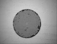
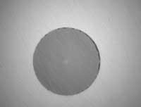
After fine polishing, inspect the fiber with a powerful microscope (200× minimum) to precisely view any scratches, pits, or damage. At this point, the fiber can be checked with a light source, such as a visual fault locator. Typical insertion loss for such connector styles as SC-to-SC or LC-to-LC can be 0.25 dB per mated pair; the manufacturer’s recommendation is 0.5 dB per mated pair.
Return loss, which is caused by the reflection at the mated joint of two connectors, is affected by the fine polishing methods and can achieve above 35 dB with diamond polishing. An additional, final finishing procedure is recommended to achieve return loss values greater than 55 dB. This is especially critical for today’s high-speed singlemode, laser-based systems.
Final finishing requires a grit size of 0.3-µm or less. Silica, aluminum oxide, and cerium oxide are preferred, again with distilled water in a wet process. The film, pad, pressure, number of “figure 8s,” together with the track and travel distance will determine the final endface shape.
More than a pretty endface
The reliability and integrity of optical-fiber connectivity depends on the degree of control taken during the polishing procedures-a significant contributor to optimal endface geometry. Too small a curvature radius and the fiber could prematurely fracture. Too large a radius introduces the possibility of reflections, which will result in high reflectivity; thus, a lower return-loss performance.
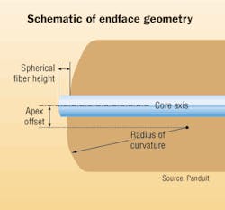
Telcordia specification GR-326-Core, Issue 3, Section 4.4.5.1 defines the shape of the connector and endface. The three metrics are apex offset (AO), radius of curvature (ROC), and the spherical fiber height (SpH). Apex offset occurs whenever the polished ferrule’s geometric peak does not correspond with the center of the fiber core. Up to 50 µm is allowable. The ferrule’s radius of curvature should be no more than 25 mm, since physical contact of the fiber endfaces could be affected. The standard specifies the fiber height to be less than 50 nm.
Because using sophisticated and cumbersome lab equipment in the field is impractical, it is difficult to check detailed endface geometry. Proper polishing techniques, therefore, become essential. Proven methods, previously mentioned, have been tested in the lab and implemented in the field. These methods should be replicated in the field for consistent high quality and desired loss margins.
Alternatives to field polishing
Successful optical-fiber connector field polishing can be achieved, provided the required tools, consumable products, appropriate manufacturers’ guidelines, and the necessary operator skill sets are used. But field polishing is just one termination style for optical-fiber connectors. Prepolished optical-fiber connectors, which can also be terminated in the field, feature a factory pre-polished fiber-stub endface. The pre-polished fiber stub in the ferrule offers comparable performance with the added benefit of eliminating time-consuming field polishing, thereby reducing installation time and cost.
Pre-polished connectors, such as Panduit’s OptiCam brand, provide a quick termination alternative to field-polish connectors. Pre-polished devices have a factory-polished endface that meets the critical geometry requirements referenced earlier, eliminating field polishing. The connectors also allow field terminating in less than half the time of field-polish connectors. With retermination capability, they also provide yield rates approaching 100%.
MANHO CHUNG is a product development engineer for Panduit. (Additional information on field polishing is available at: www.panduit.com/polishing)

