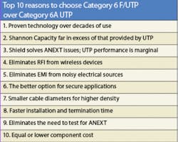
Why shielded twisted-pair matters for 10GBase-T
Considering performance, density, and speed of installation, the advantages of foiled cable are undeniable.
While Category 6A unshielded twisted-pair (UTP) cabling is getting a lot of attention these days, we believe foiled UTP (F/UTP) is a more viable alternative for running 10-Gigabit Ethernet (10-GbE) over copper. Elimination of alien crosstalk (ANEXT) concerns, smaller cable diameters, and recent technological advancements actually make F/UTP a better-performing and more cost-effective choice for 10-GbE over twisted-pair copper in many scenarios.
Several organizations are already standardizing on F/UTP solutions, and as the deployment of 10-GbE over copper continues to grow, so will the use of F/UTP cabling.
In the mid-1980s, shielded cable in the United States included the traditional IBM 150-Ω Type 1 cabling. These stiff, black cables contained two data-grade shielded twisted pairs intended for use in Token Ring networks. While Token Ring only supported network speeds of 4 and 16 Mbits/sec, Type 1 cabling provided excellent performance and was capable of carrying 300-MHz signals. Unfortunately, these cables were very rigid, difficult to connectorize, and incompatible with today’s 100-Ω LAN technologies.
When Category 3 UTP was introduced and the first TIA/EIA-568 standard was published, the U.S. turned away from shielded cabling for most LAN applications. While UTP has dominated the U.S. market ever since, it has gone through several iterations to improve electrical performance-Category 3, 4, 5, 5e, 6, and now 6A.
Preferred for its security and immunity to electromagnetic interference and radio-frequency interference (EMI/RFI), shielded twisted-pair cabling has remained the cabling of choice in many European nations, where it accounts for more than 50% of the market share. For decades, shielded cable has provided proven, robust performance in that part of the world. In the U.S., shielded cabling has primarily been deployed where EMI/RFI and security are of the utmost concern, such as government and casino installations or noisy industrial or hospital environments. These customers have also benefited from shielded cable’s superior performance.
Coming to terms
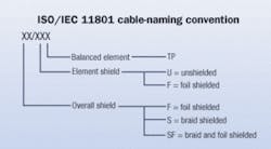
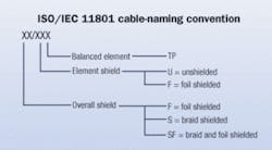
There are basically three types of shielded cabling, and the nomenclature can be confusing. The acronym “STP” can be sued to refer to any shielded twisted-pair cabling but, historically, it was also used to refer to the traditional IBM Type 1 cabling. The latest designation from ISO/IEC has the first letters indicating the type of overall shield, while the following letters indicate the type of shielding on each pair and the balanced element.
In the U.S., the most common type of shielded cabling is F/UTP-foiled unshielded twisted pair, which consists of four unshielded twisted pairs surrounded by an overall foil shield. F/UTP has also been referred to as ScTP (screened twisted pair) and FTP (foiled twisted pair).
In Europe, the primary shielded cable type is S/FTP, which consists of four foil-shielded-twisted pairs surrounded by an overall braided shield. This fully shielded cable is rated Category 7 and often referred to as PiMF (pairs in metal foil), or SSTP. While Category 7 cable offers superior performance, it is a more expensive option and will take up a considerable amount of additional space in pathways.
All-around performance
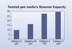
Shannon’s Law defines the maximum amount of data transmitted in the presence of noise without error, and to carry a 10-Gbit data signal, a cable must have between 16 and 18 gigabits of Shannon Capacity. Recent testing demonstrates that Category 6A F/UTP provides 27.7 Gbits/sec Shannon Capacity compared to 16.4 Gbits/sec for Category 6A UTP. In a nutshell, that 11 Gbits/sec means better signal performance and higher network speeds with fewer bit errors. Furthermore, 27.7 Gbits/sec is plenty of Shannon Capacity to run 10GbE and more.
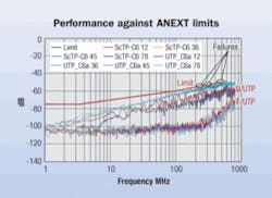
Our industry acknowledges that ANEXT is the single most critical factor in running 10-GbE over copper. ANEXT is the undesired coupling of signals between adjacent cables, which cannot be cancelled by the digital signal processing (DSP) technology at the switch level.
According to the standards, the only solution to the ANEXT problem is to provide increased separation, shielding, or improved cable constructions. Available Category 6A cables primarily use space to migrate the effects of ANEXT, but their performance is marginal at best.
The shield in a F/UTP cable does a much better job of eliminating ANEXT. Third-party testing has shown F/UTP cables to have a 20-dB improvement in ANEXT over Category 6A UTP cables on the market. The result: Shielded provides significantly more headroom for 10-GbE over copper applications.
In F/UTP cabling, the foil shield that surrounds the pairs also acts as a reflective barrier, which prevents EMI/RFI from coupling onto the twisted pairs. This essentially eliminates the effects of electrical noise from sources, such as generators, factory machinery, and large inductive loads. Due to the frequency range in which 10-GbE operates, everyday devices such as cell phones, wireless access points, and radios are now sources of noise, referred to as background noise.
When it comes to choosing between shielded and UTP cabling, it’s important to consider that our airwaves will become even more populated with wireless communication devices, which has the potential for more data contamination due to EMI/RFI and background noise. With security concerns heightened, the foil shield also prevents signals from leaking out of the cable, making it difficult to tap with an outside source.
Importance of OD
Today’s F/UTP cabling is a far cry from the bulky, stiff IBM Type 1 cabling of the past, and it’s almost as flexible as UTP. Nevertheless, many opponents to shielded solutions continue to claim that F/UTP cable is larger and more cumbersome than UTP. It’s simply not true.
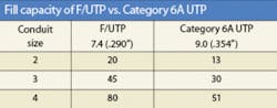
Because most Category 6A UTP cable uses space to mitigate the effects of ANEXT, these solutions have larger cable diameters-up to as large as 0.375 inches in outside diameter. At just 0.29 to 0.30 inches OD, F/UTP cable actually has a smaller outer diameter than the smallest available Category 6A UTP.
The larger diameters of Category 6A require more space for cable management in the rack and pathways-and space is expensive. The loss of density in conduits, raceways, cable trays, cable management, and firestopping costs money. While the world is adopting smaller, high-density solutions for space savings, Category 6A UTP has become larger.
On the other hand, smaller-diameter shielded cables provide port density equivalent to current Category 6 UTP and require less pathway space. This is ideal for data center applications where space is always a concern and where the first 10-GbE-over-copper applications will be deployed. F/UTP cables provide 50% more fill capacity than Category 6A UTP based on a 40% fill ratio.
The industry has also been concerned with keeping Category 6A UTP cables randomly separated in pathways to further mitigate ANEXT. But our industry has always worked in a world of cable bundles. F/UTP cables never require space for random separation to mitigate ANEXT, because the foil shielding already does the job.
There is also a major concern within the industry regarding how the effects of ANEXT can influence performance when mixing different categories of UTP cables operating at dissimilar frequencies. It is, therefore, recommended that Category 6A UTP cables running 10-GbE not be mixed in the pathway with other types of cable (including Category 6 and Category 5e) that are running standard 10/100/1000-Mbit/sec Ethernet, voice, or audio signals.
But this is simply a non-issue for F/UTP.
Faster installation time
Shielded cabling has long been perceived to take more installation time than UTP equivalents. But when we compare F/UTP to Category 6A UTP for 10-GbE, this is no longer the case. First of all, the smaller diameter of F/UTP cables makes them easier to install, and less space is required to maintain proper bend radius around corners.
Just like no-epoxy/no-polish fiber connectors, new advancements in tooling options and connector technologies have also dramatically reduced termination times of F/UTP cables. Some brands of shielded jacks, including our own, can be terminated in less than 90 seconds. With the larger gauge size of Category 6A conductors and a lack of associated termination tools available, most installers will initially be faced with a four- to five-minute termination time per Category 6A UTP jack. In other words, today’s F/UTP cable can be terminated three to four times faster than Category 6A UTP.
When it comes to grounding and bonding requirements for F/UTP cables, the procedure is straightforward and essentially no different than what is required for UTP systems. The grounding and bonding requirements specified in the current TIA J-STD-607-A Commercial Building Grounding (Earthing) and Bonding Requirements for Telecommunications are applicable to both F/UTP and UTP systems. It doesn’t matter which type of system you are installing.
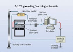
For both F/UTP and UTP, any metallic component in the telecommunications room (TR) that is attached to the cabling infrastructure must be bonded to the telecommunications grounding busbar (TGB) per the TIA standard. Shielded patch panels, jacks, and cable have the grounding and bonding built in. So, once the cable is properly terminated to the jack and the jack mounted to the patch panel, bonding and grounding is complete.
Grounding and bonding the shield at the workstation is more straightforward than many might think. In a permanent link, the shield is already bonded at the TR end, and the workstation end is not bonded to ground. This is the same for both UTP and STP systems. In a channel, the bonding of the permanent link shield to ground at the workstation end is accomplished by connecting a shielded patch cord between the outlet and the equipment. This results in a ground condition at both ends of the channel.
In a F/UTP system, the shield should completely surround the cable along its entire length, and the shield should remain continuous along the entire length of the channel. This is accomplished by using only shielded products throughout the entire channel, from cable to plug to jack to patch panel. When terminating a shielded jack, the shield must make contact with the connector. Because today’s shielded connectivity hardware is made completely of metal, ensuring that contact is simple. Some jacks, for example, feature a spring-loaded cable strain relief that automatically provides a 360º contact to the terminated shield.
Another time saver for F/UTP installations is the elimination of field testing for ANEXT. For 10-GbE applications, Category 6A UTP cables will have to be tested for ANEXT-a complex and time-consuming process requiring the measurement of all possible wire-pair combinations for NEXT between two cabling links and the use of two testers connected at different ends of a bundle to measure pair-to-pair alien far-end crosstalk. It requires approximately 50 minutes to fully test one link in a bundle of 24 Category 6A cables. Because this field testing is not necessary with shielded systems, testing time is significantly decreased and overall installation time further reduced.
Cost effectiveness
While the cost of F/UTP components have typically been higher than Category 6 UTP, that is not the case when compared to Category 6A. In a recent price comparison with four Category 6A UTP solutions, we found Category 6A F/UTP components to be equal, and in some cases less, than Category 6A UTP. But cost effectiveness is not just about component cost; it’s also about total cost of ownership. When you consider the better performance, smaller cable diameter, and faster installation time, it is easy to conclude that a shielded cabling system is more cost-effective than Category 6A UTP for 10-GbE over copper applications.
While demands for UTP systems continue, many customers, vendors, and standards bodies are taking note of shielded’s advantages for running 10-GbE over copper. And even if the network requirements never reach 10 Gig, shielded customers will still have a robust, immune cabling infrastructure that is much more “futureproof” than UTP-just like those in Europe who have embraced shielded technology for years.
We foresee increasing bandwidth demand and the limits of UTP to continue driving the growth of F/UTP solutions in the market. In the meantime, if you’re considering implementing a 10-GbE copper solution, keep in mind that early technology adopters like hospitals, the military, casinos, and financial institutions are already standardizing on shielded solutions-and that equipment manufacturers view shielded as a viable choice.BRIAN DAVIS, RCDD is a premises connectivity product manager and BOB ZAHR, RCDD/NTS is a systems engineering manager with Tyco Electronics’ AMP Netconnect division.

