Rethinking field testing for alien crosstalk

10-Gbit/sec deployment has sparked less intrusive and faster testing methods, as well as some tried-and-true counsel on installation guidelines.
The Institute of Electrical and Electronics Engineers (IEEE; www.ieee.org) is expected to release the standard for the next generation 10-Gbits/sec copper cable Ethernet network-termed 10GBase-T-later this year. For deployment of 10-Gbits/sec on an Augmented Category 6 cabling system, one key issue is the testing and management of the noise coupled between the adjacent link segments, an example of what is known as alien crosstalk.
Here is a look at alien crosstalk testing for 10-Gbits/sec transmission, its challenges, field-testing approaches and mitigation recommendations.
The 10GBase-T cabling system
With continual evolution, Ethernet has matured into the leading technology standard for LANs. Newer, higher-performing versions (such as 10-Gigabit Ethernet) are becoming more commonplace.
Since 2004, the IEEE 802.3an task force has worked on a project called 10GBase-T-a 10 Gbits/sec Ethernet over UTP copper LAN standard. The goal is to approximate 8-pin modular (RJ-45) connectivity of 100 meters, and is intended to improve the performance and distance of copper cabling at a cost that is lower than or similar to fiber.
Category 5 and Category 6 are the most common cabling systems being installed today, but are not capable of meeting the bandwidth and crosstalk demands of 10-Gbit Ethernet’s higher transmission speeds. To meet the needs of 10-Gbit Ethernet, a Telecommunications Industry Association (TIA; www.tia.org) subcommittee for cabling specifications (TIA 42.7) is working to provide additional specifications that will help vendors create sufficient cabling.
Presently, the TIA is developing ANSI/TIA TSB 155, “Guidelines for the Assessment and Mitigation of Installed Category 6 Cabling to Support 10GBase-T.” This document gives guidelines to further characterize Category 6 cabling systems for 10GBase-T applications for up to 55 meters (m) of cable. At the request of the IEEE, the TIA is also working on ANSI/TIA 568-B.2-10, “Transmission Performance Specifications for 4-Pair 100-Ohm Augmented Category 6 Cabling,” for 100-m channels specified to 500 MHz.
Alien crosstalk factors
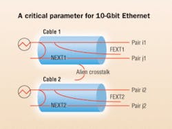
Alien crosstalk, or the noise coupled between the adjacent cables, is a critical parameter of the cabling system for 10GBase-T applications.
Alien crosstalk noise levels are dependent on the number and proximity of adjacent cables and connectors. The coupling model is complex. Some important factors include:
• Separation of cable to cable or port to port;
• Distance from the source where the coupling begins and cable length;
• UTP twist density;
• Number of cables crosstalking into the target cable;
• Magnitude and frequency of the source signal.
Basically, the two metrics of alien crosstalk are power sum alien near end crosstalk (PSANEXT) and power sum alien equal-level far-end crosstalk (PSAELFEXT), which represent the cumulative effects of near-end and far-end alien crosstalk from all disturbing channels.
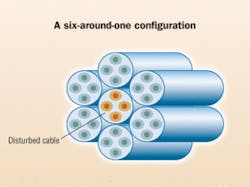
Typically, in a lab environment, the measurement of PSANEXT and PSAELFEXT are based on cables configured in a six-around-one orientation, where the victim or target cable is the central cable and adjacent to all of the others called disturbing cables. The alien crosstalk coupling between a cable and six surrounding cables tightly bound in a six-around-one configuration exhibits a “worst case.” Cables not in direct physical contact with the target cable generate much lower crosstalk and can be disregarded in comparison to the worst-case scenario.
Alien crosstalk between cables reduces the operational bandwidth of a cabling channel because of an increased level of crosstalk noise, decreasing the overall signal-to-noise ratio. For higher-bandwidth applications like 10GBase-T, its effects are much more severe than for lower-speed network applications.
Furthermore, unlike in-channel (pair-to-pair) crosstalk (NEXT/FEXT), which can be suppressed with digital signal processing (DSP) technology built into the physical layer networking devices, alien crosstalk is too difficult to be cancelled without adding enormous cost and complexity to the design of the transceiver.
While managing alien crosstalk has become critical in the deployment of 10GBase-T, there has also been recent increased interest in the technologies that look at this problem. In particular, since alien crosstalk management depends on testing, attention to field testing alien crosstalk is growing from all corners of the market.
The challenges of measuring
Consider the difference between alien crosstalk testing and in-channel crosstalk testing of a cabling system.
In-channel crosstalk testing is done only on one cable under test. Alien crosstalk testing, on the other hand, is carried out between one target cable and multiple disturbing cables (six is the typical number, as shown in the figure, “Six-around-one configuration”). Alien crosstalk testing, therefore, needs more than just two cables to be connected to test equipment.
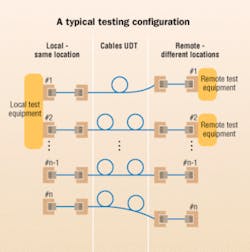
For in-channel crosstalk testing, only one local and one remote piece of test equipment are needed. But for alien crosstalk testing, multiple cables under test may be at different locations. This topology calls for a test instrument at each of the remote ends.
In summary, the alien crosstalk test setup is more complex than that of in-channel crosstalk testing. Furthermore, more test instruments are needed for alien crosstalk testing than in-channel crosstalk testing. The challenge is to provide a low-cost solution that is able to support this complex testing requirement.
The second and bigger challenge is the field test procedure itself. Alien crosstalk field testing should be executed for a bundle of cables, which may include more than six cables.
If a solution only supports testing two cables at a time, you’ll have to connect and disconnect cables repeatedly. Besides being a highly manual intervention, this is a time-consuming process that carries a high possibility of human error. Unless you follow a rigorous tagging system, there is a chance you will forget some combinations.
Measurement combinations increase rapidly with the number of cables. For n cables, the PSANEXT testing will involve n(n-1)/2 combinations. For example, for seven disturber cables, 21 individual ANEXT measurements are required.
Varying approaches
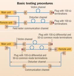
Recent solutions for alien crosstalk testing are mostly based on the existing solution for the normal crosstalk measurement. Two solutions in use today are based on two test devices connecting the victim and disturber cables under test, respectively-a communication channel between the two devices.
For near-end alien crosstalk testing, the main unit is connected to the victim channel, and the remote unit is connected to a disturber channel. The remote ends of the victim and a disturber pair are terminated with specific termination, including a 100-Ω differential and 50-Ω differential termination. During testing, the remote unit simultaneously transmits a stimulating signal, pair-by-pair, in the disturber cable; and the main unit measures the coupled alien crosstalk, pair-by-pair, on the victim cable.
For far-end alien crosstalk testing, the main unit is connected to the victim cable and the remote unit is connected to a disturber cable. This is assuming that a main and remote unit have a separate measurement control communication path connection.
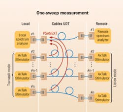
A patent-pending solution is based on a new tool called an Alien Cross Talk Stimulator (AxTalk Stimulator). The victim cable is connected with a handheld spectrum analyzer at each end. All disturbing cables are connected with stimulators at both ends.
To understand this new approach, it is helpful to know that the stimulators can communicate and work in three modes:
• Transmit mode: Transmits an RF signal with a specific pattern when one on the other end is in listen mode.
• Termination mode: Both units switching to the 100-Ω and 50-Ω differential terminations, which is the default state supporting communication between local and remote stimulators.
• Listen mode: Switching to termination when the remote unit is in transmit mode.
For the Power Sum Alien FEXT testing, the roles of local and remote stimulators are reversed.
Alien crosstalk testing based on this setup works on the frequency domain principle, which means a transmitter produces a sinusoidal test signal at each frequency of interest for a specific duration. The frequencies of interest are defined by the governing standard (e.g., TIA 568-B.2 [4]). The test signal is then applied to a device under test (e.g., a cable pair), and the coupled alien crosstalk signal is received by the local or remote spectrum analyzer, which is tuned to the same frequency.
Based on specific frequency sweep technology, the alien crosstalk from any number of disturber cables with stimulators attached can be measured in only one measurement sweep, which typically takes several minutes. This eliminates the need to connect and disconnect the disturbing cables one at a time, and provides a quick way to identify the disturbing cables’ coupled alien crosstalk noise.
Mitigating alien crosstalk
Measuring alien crosstalk noise is useful in true 10GBase-T deployment. Because 10GBase-T is designed to operate over a channel that meets the specifications defined in ANSI/TIA 568-B.2-10,if the channel specifications of alien crosstalk cannot be met, alien-crosstalk mitigation technology is necessary.
The first aspect of mitigating the alien crosstalk is to use cabling products designed to be robust against the effects of alien crosstalk.
Another approach, which is easier and more practical, is based on the proper installation of a 10GBase-T cabling system. Some guidelines are:
1. When deployment of applications needing 10GBase-T is possible, use non-adjacent patch panel positions and separate the equipment cords (patch panel adjacency should also be checked at the rear of the patch panel). The adjacent positions may be used for other applications, such as 10/100/1000Base-T.
2. When deployment of applications needing 10GBase-T in adjacent patch panel positions in the telecommunications room is required, identify measured patch panel positions to be included in the power sum alien crosstalk.
In the event that the measured alien crosstalk transmission parameters are not meeting the limit, alien crosstalk may be mitigated by following these steps:
• Reduce the alien-crosstalk coupling by separating the equipment cords and the patch cords, and un-bundling the horizontal cabling.
• An alternative to separating equipment cords is to use equipment cords sufficiently specified to mitigate the alien-crosstalk coupling, such as Category 6 ScTP and Augmented Category 6.
• Reconfigure the cross-connect as an interconnect.XING ZHU and HARSHANG PANDYA work in R&D at the Photonics Measurement division at Agilent Technologies (www.agilent.com) in Singapore. Xing can be reached at [email protected]. Harshang can be reached at [email protected].

