New wireless guidelines promote more cabling

TIA’s imminent TSB-162 complements RF planning and offers a new approach to wireless grid cabling, all in accordance with existing TIA standards.
Expected to be available in the forthcoming months, the Telecommunications Industry Association’s (TIA; www.tiaonline.org) Telecommunications Systems Bulletin TSB-162 Telecommunications Cabling Guidelines for Wireless Access Points (APs) provides guidelines on the topology, design, installation, and testing of cabling infrastructure for supporting wireless local area networks (WLANs) in accordance with the ANSI/TIA/EIA-568-B.2 and TIA-569-B standards. While previous standards bodies have addressed planning for cabling to APs, TIA’s TSB-162, officially approved last October, includes its own pre-cabled grid guidelines and reference to existing TIA standards.
Subtle changes
One of the first documents to specifically address connections to APs was ISO/IEC TR 24704, which was published in March 2004. Shortly after the release of the ISO document, TIA began work on its own document to address cabling for APs.
“We recognized the success of the ISO document, but ISO standards are not always specified in the U.S.,” says Bob Jensen, standards development and technology manager for Fluke Networks (www.flukenetworks.com). “Because TIA standards are well known in the U.S., we believed that our market would greatly benefit from a wireless document under TIA.”
Initial thoughts within the TIA task group responsible for producing TSB-162 were to simply adopt the ISO/IEC TR 24704 document. But as the committee began reviews and discussions, they discovered subtle ways to enhance the guidelines. “There were no issues or concerns with the existing ISO document, and while the two documents are only slightly different, I believe the changes that came about are for the better,” says Jensen.
While the ISO/IEC document refers to the need to test cabling and meet specifications, TSB-162 states that cabling should be installed and performance tested per existing 568-B.2 standards.
“Specific performance specifications for testing the channel and the permanent link is not something that the ISO/IEC document provided,” says Bob Elliot, product development manager for Panduit (www.panduit.com). “Because the TSB is in line with existing TIA standards, we can now ensure that the cabling for APs meets the same Category 5e and Category 6 requirements as the rest of the network cabling. It’s a way for AP cabling to fall under 568-B.2.”
The wireless cell shape is another major difference between the TSB-162 and existing ISO/IEC document. The ISO/IEC TR 24704 document incorporates a hexagonal wireless cell structure that, when grouped together, resembles a honeycomb. TSB-162, on the other hand, uses square cell sizes that form a grid cabling architecture for WAPs. The telecommunications outlet (TO) is located in the center of the cell.
“The honeycomb layout in the ISO/IEC document didn’t really lend itself to the building construction design that we find here in the U.S.,” says Jensen. “When you look at North American commercial building construction, buildings are typically laid out with columns that form approximate 30-foot by 30-foot bays.” In U.S. commercial building construction, outside and inside walls and areas are almost always square; therefore, a square wireless cell structure makes designing a wireless network much easier.
According to Elsa Madrigal, research engineer for Panduit and a member of the committee that developed TSB-162, designing a wireless network with the TSB-162 cell structure is ideal for “greenfield” deployments. “When a brand new building is being constructed, and only the main building columns have been determined, deploying a square wireless cell structure helps designers determine approximately where APs will be located for seamless wireless coverage,” says Madrigal. “The result is an upfront approximation of how many APs and how much cabling will be required for the WLAN.”
Staying within the scope
But when it comes to determining the actual cell size and placement of the AP within the cell, there are many other influencing factors that are outside the scope of TSB-162. Because the purpose of TSB-162 is strictly to provide guidelines on cabling for APs, determination of exact cell size and placement of the AP is outside the scope of the TSB. According to Ray Emplit, standards and technical representative for Wiremold/Legrand (www.wiremold.com), many factors can influence AP performance and placement.
“Things like building materials, space configuration, furnishings, RF [radio frequency] design, and occupant density can all impact determining the size of the wireless cell structure,” says Emplit. “All of those factors are outside the scope of the TSB, which is why the TSB recommends the use of an RF planner.”
RF planners conduct comprehensive site surveying of the WLAN to determine signal strength, capacity, and roaming in attempts to meet bandwidth and user requirements, and to provide seamless coverage as users move around an area. TSB-162 includes many references to the importance of using an RF planner to ensure that wireless needs are met.
The TSB does include an example of a 60-foot by 60-foot square cell structure, based on the 30-foot by 30-foot bay size of U.S. commercial buildings and coverage area of today’s APs. A 60 by 60 cell could be made up of four 30 by 30 bays, with the TO located at the center column. Because exact cell size determination is outside the scope of the document, the TSB also includes guidelines for creating custom cell sizes. “You may have a building, like a hospital or school, where you cannot design a 60 by 60-foot grid,” says Madrigal. “You may have to reduce or increase the size of cells based on individual needs.”
While TSB-162 cannot tell you your exact cell size or where to place your AP within the cell, it does provide information on determining the length of the patch cord used to connect the AP to the TO in the center of the cell. “The use of a patch cord between the TO and the AP enables moving the AP around within the cell for specialized coverage,” says Madrigal. “Plus, physical limitations may cause the AP to perform better in one part of the cell versus another.”
The maximum length of the patch cord is equal to the cell radius, which is limited by the horizontal link length based on existing TIA multi-user telecommunications outlet assembly (MUTOA) calculations. “Once the cell size is determined through RF planning and individual needs, that size is used to calculate the maximum radius or patch cord length from the TO to the AP,” says Emplit. “Once the patch cord length is determined, the existing TIA calculations for the MUTOA are used to determine the horizontal link length.”
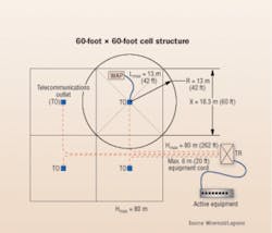
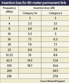
In the 60-foot by 60-foot cell size example, the circle encompassing the square cell has a radius of 42 feet (13 meters), which is the patch cord length (calculated using the Pythagorean Theorem of c2 = a2 + b2). Using the MUTOA calculations specified under 568-B.2, the maximum horizontal link length for the 60-foot by 60-foot cell is 262 feet (80 meters). Permanent link insertion loss calculations for both Category 5e and Category 6 are also provided in TSB-162 to account for the shorter horizontal link lengths. (See table, page 40.)
For information only
In addition to copper testing guidelines in accordance with existing TIA standards and guidelines for determining cell size and radius, TSB-162 includes information on power and mounting options, as well as an annex that covers other non-grid cabling options.
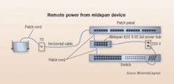
“Power over Ethernet is mentioned in this TSB as an option, but it is more of a reference to what technologies are available versus actual specifications,” says Panduit’s Elliot. TSB-162 includes information and diagrams that explain various power options, including remote PoE power from a switch or midspan device and local AC power. “Power over Ethernet patch panels can also be used to provide power to APs,” says Elliot. “These devices save space by locating the demarcation point in the same device as the power, and also eliminate extraneous patch cords.” Elliot adds that PoE patch panels also enable control of the power being provided to individual ports, allowing devices, such as APs, to be remotely power-cycled, if necessary.
Mounting options in TSB-162 include wall-mount above the drop ceiling, wall-mount below the drop ceiling, and in-grid ceiling mount. The use of a telecommunications enclosure (TE) is also mentioned. “TEs can be mounted in a ceiling panel to provide locked security or aesthetics for APs,” says Jensen. “TEs typically include access holes where antennae can be extended out into the open space to send and receive RF signals. TEs also employ an electrical circuit that can be used to power the AP in addition to other electronics.” Jensen says TSB-162 also provides basic information on the different types of AP antennae available.
“The great thing about this TSB is that it complements the RF planner’s job,” says Panduit’s Madrigal. “Because wireless is a new technology, and this TSB is strictly about cabling, the committee had to walk a fine line on many issues and make sure to consistently recommend the use of an RF planner. But in terms of cabling for APs, I believe it’s a complete and useful document.”
Jensen adds that TSB-162 is an informational document that promotes more cabling within commercial buildings. “With the publication of this TSB, additional cabling will be recommended over the current requirements of the TIA 568-B standard,” Jensen says. “The additional cabling will aid users in their flexibility to move wirelessly from office to conference room, yet ensuring their full bandwidth capability at their wired desk. In the future, we may see TSB-162 become integrated into the next revision of the 568 standard.”BETSY ZIOBRON is a freelance writer covering the cabling industry, and a frequent contributor to Cabling Installation & Maintenance. She can be reached at: [email protected]

