A standards-based design in the data center
A TIA standard simplifies design and management of much-needed structured cabling systems inside data centers.
Data centers and storage area networks (SANs) are among the fastest growing areas of information technology (IT). It is generally believed, and a 2004 study by Yankee Group indicates, that data creation and retention requirements in large enterprises are growing at 50% per year. This growth is due to a multitude of legislative and financial agreements in the United States and abroad, which are dictating how much information must be stored, how it is stored, and for how long.

For example, the Sarbanes-Oxley Act requires publicly held companies with a market capitalization greater than $75 million to retain documents related to financial statements for seven years, effectively requiring top management to sign for the financial accuracy of the company’s annual reports, and holding them accountable for the practices and procedures in their IT departments. The new “Rule 17a” of the U.S. Securities & Exchange Commission (SEC) establishes strict requirements for brokerage and stock exchange members. Under the new rule, a six-year retention period is required for transactions, e-mails, and instant messages.
These and other laws and international agreements have fueled growth of data centers and SANs.
The need for structured cabling
Historically, data centers an SANs have often been constructed without full consideration of the implications of frequent capacity expansions and the resultant moves, adds, and changes (MACs) that occur over their lifecycle. Some systems, such as computers and SANs, may be installed and cabled by the manufacturer’s own technicians. While these crews likely are competent with their own systems, the data center may contain a mix of disparate technologies. Using such practices inevitably leads to cabling systems without the manageability critical for rapid maintenance, upgrades, and the introduction of new products and technologies.
In the early 1980s, when AT&T divested the Regional Bell Operating Companies (RBOCs), ownership of cabling systems within commercial buildings passed from the regional companies to building owners. A wide variety of proprietary cabling systems and architectures were common, but difficult to manage. This undesirable situation led to the development of the TIA/EIA-568 Commercial Building Cabling Standard, which introduced the concept of the structured cabling system (SCS), and permanently changed and dramatically improved the way telecommunications and data equipment within commercial buildings are cabled and managed.
Standard brings simplification
The optical-fiber and unshielded twisted-pair (UTP) copper industries have developed and introduced many new cable and connectivity products, offering specific advantages for data center and SAN applications. During the past few years, subject matter experts (many of whom helped developed the TIA/EIA-568 standard as well as its successors TIA/EIA-568-A, B, and the emerging C) developed a new SCS standard tailored to the requirements of data centers and SANs.
The new standard, TIA-942 Telecommunications Infrastructure Standard for Data Centers, is expected to benefit data center and SAN design as profoundly as the TIA/EIA-568 series of standards benefited commercial buildings.
This new standard finally allows data center designers to incorporate SCS concepts to efficiently integrate disparate data center/SAN systems early in the building design process. The standard views the data center/SAN as a fully integrated system comprising many components. As a result, it covers many interrelated technologies, such as network design, location, and access, as well as architectural and electrical systems and the crucial element of redundancy.
Spaces and subsystems
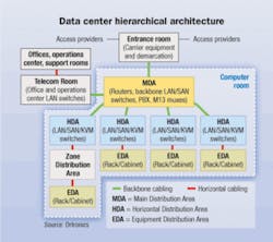
TIA-942 defines seven “spaces” and two “cabling subsystems” within the data center. The spaces include:
• Computer room;
• Telecommunications Room (TR);
• Entrance room;
• Main Distribution Area (MDA);
• Horizontal Distribution Area (HDA);
• Zone Distribution Area (ZDA);
• Equipment Distribution Area (EDA).
The cabling subsystems defined by TIA-942 include the backbone and the horizontal.
The figure on page 29 shows the relationship of the spaces and cabling subsystems in a typical data center, such as used by an enterprise or Internet Service Provider (ISP). The first five “spaces” generally involve many connections and are best supported with high-capacity, high-density patch panels and racks using small-form-factor (SFF) fiber connectors, such as the LC (pictured above).
To better understand TIA-942, it is helpful to look at the analogies between data center subsystems in a traditional commercial building and those in a data center. The data center entrance room is the interface with the campus, service- and access-provider facilities, and is analogous to the entrance facility in the building TIA/EIA-568-A cabling standard.
The data center MDA is where the main cross-connect is located, and is similar to the equipment room in the building cabling standard. The HDA is the location of the horizontal cross-connect and is analogous to the telecommunications room (TR) in the building cabling standard. The TR in 942 has a different meaning, as it is the office and operations center. The ZDA is an optional “space” in the data center standard and is where the zone outlet is located. It’s analogous to the consolidation point in the building cabling standard. And finally, the EDA is where the cabinets, racks, and servers are located. It is analogous to the work area in the building cabling standard.
Centralized fiber-optic cabling
The data center standard also includes the option of centralized fiber-optic cabling. A similar architecture is also supported in the latest 568-B building cabling standard and international ISO 11801 2nd Edition equivalent. It allows an alternative to optical cross-connection in the HDA, replacing it with a simple splice or interconnect.
With centralized cabling, no electronics are required or located in the HDA. Instead, the electronics are centralized in the MDA. There are significant cost benefits to this type of architecture, including a smaller and less complex HDA and fewer idle ports, since the ports are aggregated in one location rather than distributed. With no electronics in the HDAs, administration is centralized and simplified. As requirements change, MACs are also simplified as active electronics are limited to two locations rather than three.
The TIA Fiber Optics LAN Section (FOLS) has developed a comprehensive cost model comparing the total installed first costs of the traditional hierarchical star architecture with the centralized fiber-optic cabling architecture. (The cost model is available for download at www.fols.org)
Selecting the optimal fiber
The most commonly used medium in data centers today is UTP copper, but the need for maximum uptime and future support for higher-speed systems is resulting in the installation of more fiber. Fiber’s many advantages may be relatively new to some data center managers, but will become increasingly important as they carefully plan for future growth. These advantages include high bandwidth, support for more protocols, immunity from electromagnetic interference/radio-frequency interference, security, performance over a wide temperature range, small cable cross-section, greater pull strength, and less air-flow obstruction.
Disruptions due to frequent recabling are less tolerable in data centers than in commercial buildings. Concern about increasing copper cable diameters and the resultant effect of large cable bundles on air flow runs counter to the higher density trend in newer and larger data centers.
Distances in data centers are typically shorter than in commercial buildings, so maximum channel “reach” is less important. Data center managers need the ability to support the full number of connections required for an easily manageable SCS.
Conventional “FDDI-grade” 62.5/125- and 50/125 µm fiber has limited ability to support 10-Gbit/sec data rates that are beginning to be deployed in new and upgraded data centers. OM3 laser-optimized 50-µm multimode fiber (LOMF) was designed specifically for data rates up to 10 Gbits/sec, offering at least a tenfold increase in bandwidth (2,000 MH·zkm) at the economical 850-nanometer (short) wavelength over FDDI-grade fiber. Some SCS fiber system suppliers offer even higher-bandwidth LOMF fiber, up to 4,900 MHz·km-almost 25 times greater bandwidth than legacy FDDI fiber.
The operation of 10-Gbit/sec fiber Ethernet systems is based on a mathematical model developed by the Institute of Electrical and Electronics Engineers (IEEE) in the 802.3ae 10GBase standard. This model includes multiple penalties, one of which-intersymbol interference (ISI)-is a function of channel length and consumes approximately 50% of the total available budget. ISI is an artifact of spreading laser pulses, which cause the binary digits (bits) to overlap across adjacent bit periods, resulting in data errors.
The high bandwidth of standards-based OM3-grade LOMF traditionally used to support long link lengths offers an equally compelling advantage when used at the shorter distances typical in the data center. The system designer can take advantage of high LOMF bandwidth by trading or “reallocating” a portion of the ISI penalty for increased channel loss. The higher the LOMF bandwidth, the greater the amount of ISI penalty that may be reallocated.
State-of-the-art LOMF enables up to an additional 1.9 dB of cable plant loss budget in addition to the 2.6 dB specified in the IEEE standard, for a total of 4.5 dB. This additional “optical headroom” supports additional connections and/or potentially higher insertion loss multi-fiber connections to provide the data center designer and manager with more flexible SCS designs.
The ability to support many channels in one small-diameter fiber-optic cable is increasingly important to data center managers. While standard fiber premises distribution cables have relatively small outside diameters, ribbon fiber cables and reduced diameter multi-ribbon cables occupy even less space. Some manufacturers’ reduced-diameter fiber-optic cables are also suitable for indoor/outdoor installations connecting campus networks, avoiding the transition to riser- or plenum-rated cable in the data center entrance room.
Conserving valuable floor space
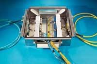
First-class data center construction costs range from $900 to $1,200 per square foot, according to a Meta Group report entitled “Room at the Data Center?” Consequently, data center designers and managers need to maximize the use of this costly real estate, and one way is through deployment of a raised-floor patch panel system in the ZDA and EDA.
Raised-floor patch panels (pictured above) are installed under a 2x2-foot raised floor tile in underfloor boxes, available from a number of manufacturers. The enclosure should be designed to minimize air flow obstruction in the plenum airspace and be sealed to isolate the plenum environment, minimizing creation of a turbulent air flow.
Fiber connections in the data center may use one or more of the following techniques:
• Optical cassettes with ribbon or reduced-diameter cables;
• Preterminated trunk cable assemblies;
• Field-terminated connectors.
For flexibility, it is recommended that the raised-floor patch panel accommodate all three options. The patch panel should also provide proper cable strain relief and fiber bend radius control. Because there are generally fewer cables in the ZDA and EDA, the raised-floor patch panel may be an appropriate choice in these areas.
Room underneath to grow
The raised-floor patch panel may be considered an enabling technology, permitting costly or otherwise impossible data center growth and expansion. Because two fiber patch panels easily fit in one underfloor enclosure, freeing up four units of rack space (4U) frees up 10% of a typical 40U rack. Deploying 10 underfloor enclosures, each containing two fiber patch panels, will free up 40U, or one full rack. If sufficient space is available under the raised floor, placing these fiber connections under the floor may permit the deployment of a full rack of active electronics.
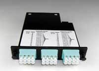
Optical cassette technology is becoming increasingly popular in the data center and SANs due to its modular design, ease of installation, guaranteed optical performance, and high reliability in mission-critical applications. The system (shown above) comprises two optical cassettes, each containing a multi-fiber MTP or MPO connector located on the rear, and discrete or two-fiber connectors (LC, ST, SC, etc.) on the front.
The two cassettes are connected with a ribbon backbone or ribbonized loose-tube cable containing 12 or more fibers that are factory-terminated with one or more 12-fiber MTP/MPO connectors. Because the MTP connectors are installed at the factory, advanced inspection techniques, such as laser interferometry, may be used to guarantee optical performance.
The multi-fiber backbone cable dramatically simplifies installation in time-sensitive data center construction and startup, as well as in restoring operation after MACs in the data center. The front connectors on the cassette provide easy connection to common equipment interfaces.
Connection flexibility
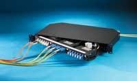
With the large amount of equipment in today’s data centers, it makes sense to standardize on fiber cabinetry that supports all three fiber termination techniques, including cassette-based, preterminated trunk cable assemblies, and field-terminated. Inventory expenses can be reduced with a flexible product that accommodates cross-connect and interconnect patching as well as splicing.
The TIA-942 standard defines multiple data center “areas,” and each potentially requires different numbers of connections. Fiber cabinets are available to support a wide range of fiber counts through consistent 1U, 2U, 3U, and 4U designs. Large cabinet chassis with bidirectional sliding trays facilitate access to rear backbone and front patch cables while providing adequate space to organize and protect the fibers.
The TIA-942 standard recommends compliance with the TIA-606-A administration standard, so the ideal fiber cabinet should provide easy, drop-down access to reusable labels. Cabinets should provide proper fiber bend radius management using easily configurable snap-in fiber management clips. Finally, they should be compatible with the racks in which they are mounted so they can provide convenient patch cord and cable routing.
In summary, vast quantities of new information are being created, stored, and communicated over increasingly higher-speed networks. Legislation and financial industry recommendations both here and abroad are having a major impact on the growth and design of data centers and SANs. The new TIA-942 data center standard finally gives data center and SAN managers guidance on how to design and implement fiber and copper structured cabling systems designed to systematically handle increasing traffic and growth.
It is important to understand the fiber, fiber cable, and connectivity technology that can most seamlessly support this growth. Carefully choosing from these options will help ensure that your new data center/SAN solution will support multiple generations of electronics for the longest cabling system lifecycle.JOHN STRUHAR is director of fiber-optic structured cabling system solutions for Ortronics/Legrand (www.ortronics.com).

