Testing guidelines for 10-GbE over twisted pairs
Certifying links for alien-crosstalk performance is more likely to be a sample process than a simple one.
The IEEE standards review board approved the standard for 10-Gbit/sec Ethernet over twisted-pair copper cabling (10GBase-T) on June 8, and we expect that the 802.3 standards documents will be updated and published sometime this year.
This article will provide a background and overview of the performance requirements for the twisted-pair cabling and methods to measure and certify the performance of the installed cabling system.
Field certification of twisted-pair cabling for 10GBase-T consists of two phases. First, all cabling links must meet the performance specified by the in-channel test parameters currently specified in the TIA/EIA-568B document for Category 6 or in the ISO 11801 standard. They are: insertion loss, return loss, pair-to-pair near-end crosstalk (NEXT), power-sum NEXT, pair-to-pair equal-level far-end crosstalk (ELFEXT), power-sum ELFEXT, propagation delay, length, delay skew, and wiremap.
The 10GBase-T test limits for these tests are identical to the limits for Category 6, but the frequency range and performance specifications are extended to 500 MHz to support the much higher bandwidth required for 10-Gbit/sec Ethernet technology. In the second test phase, an additional phenomenon called alien crosstalk must be tested and included with the field certification effort for 10-Gbit/sec Ethernet.
Understanding crosstalk’s impact
10GBase-T signaling requires cabling bandwidth up to 500 MHz, which is much higher than the 100-MHz bandwidth required for 1000Base-T. Because of these very high frequencies, one significant new disturbance must be added to the cabling test parameters-alien crosstalk, which refers to the signal coupling between cables in a bundle.
Crosstalk measures signal coupling from one wire pair to another within a twisted-pair cabling link. This kind of coupling is undesirable because it creates a noise disturbance in the wire pair. The effect of crosstalk is similar to a noisy transmission line. A receiver may not be able to distinguish the signal sent by the transmitter at the other end of the link from the noise induced by crosstalk. In data communications, crosstalk is a critical performance parameter.
Two effects are at work to limit the usable bandwidth of a twisted-pair cabling link. First, the strength of a signal arriving at the end of the transmission link (input to the receiver) diminishes as the frequency of the signal increases. Expressed in cable-testing terms, the insertion loss (attenuation) of the transmitted signal increases as the frequency of the signal increases. At the same time, the crosstalk between wire pairs increases as the frequency of the transmitted signal increases.
The combination of these two effects is why we will find a frequency at which the noise created by crosstalk equals the signal received from the transmitter. This frequency is typically around 120 MHz for Category 5e channels that approximate 100 meters in length, and around 240 MHz for full-length Category 6 channels. Without sophisticated digital signal processing techniques in the electronics, reliable transmission is no longer possible around this “crossover” frequency and for higher frequencies. This phenomenon sets a limit in bandwidth for twisted-pair cabling.
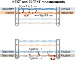
NEXT measures the crosstalk signal that appears at the same end of the cabling link from which the test signal or disturbing signal is launched. If transmission simultaneously takes place over multiple wire-pairs as is the case in 1000Base-T and 10GBase-T, FEXT must also be considered and tested.
Alien crosstalk is essentially the same phenomenon as the NEXT and ELFEXT depicted in the first figure (page 36), but in this case, the crosstalk coupling now occurs between wire-pairs in different, adjacent cabling links.
Alien crosstalk is a challenge for twisted-pair cabling since it is the most significant disturbance or noise source for the 10GbE application over UTP cabling. Alien crosstalk will be measured as alien NEXT between pairs as well as alien FEXT. Because it is necessary to assess the combined impact of many wire-pairs in the bundle upon the wire-pair under test (usually referred to as the “victim” wire-pair), power-sum alien NEXT (PSANEXT) and power-sum alien FEXT (PSAFEXT) must be computed and evaluated for wire-pairs in a cabling bundle.
Testing alien crosstalk
What follows is one method to measure alien crosstalk components, as well as a test strategy:
The measurement method describes the hardware and software configuration of the test tools to measure the crosstalk between wire pairs in adjacent cables. The test strategy discusses the way in which the test of a cabling installation may be approached. In most cases, it is not economically feasible or affordable to test the alien crosstalk between all possible wire-pair combinations.
When certification testers are used to test a cable’s NEXT performance, the main and remote are connected at either end of the same cable and the two units use the link-under-test to synchronize their measurement processes. To measure alien NEXT, the main and remote tester units need to be connected to different cables.
A method must be provided between the main and remote units to allow these two units to synchronize the measurement process. In the case of the Fluke Networks DTX-1800 (the tester depicted in this article), a special alien crosstalk communication module plugs into the back of the units, in the same place where a fiber-optic loss test module can be inserted. (Note: The method described here does not necessarily apply to other tester units. Ensure that you follow your tester manufacturer’s directions for testing alien crosstalk.) After each unit has been equipped with an alien crosstalk module, you can use a standard patch cord to connect these two modules and complete the linkage required for the measurement synchronization. The far ends of the cabling links-under-test are now not connected to a tester unit.
An open circuit at the far end of a link creates a very significant reflection of the test signals. So, a special termination plug must be installed at the end of these two links to avoid reflections from the far end, which would interfere with the measurement process and jeopardize its accuracy.

All the possible wire-pair combinations for NEXT between two cabling links total 16 combinations, and all are to be measured and evaluated over the frequency range of 1 to 500 MHz.
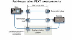
To measure the pair-to-pair alien FEXT between cables in a bundle, the two tester units must be connected at different ends of the bundle. The tester units must also be configured with the same alien crosstalk communication modules used for alien NEXT measurements. A spare cabling link or a link that is not used in the measurements can be used to provide the synchronization path between the main and remote tester units. The open ends of the links involved in the test must be terminated by the same type of plug used for alien NEXT testing.
This method has been used in the field with good results. In this test setup, a significant performance parameter is the noise floor, which allows the tester to accurately measure the small pair-to-pair alien crosstalk signals.
Power-sum measurements
As mentioned, alien crosstalk evaluation of a cabling bundle does not stop with the measurement of the alien crosstalk coupling between individual wire pairs. During full network operation, all wire-pairs in a cabling bundle simultaneously transmit in full-duplex mode (signals flow in both directions on each wire-pair). Therefore, any one wire-pair will be affected by transmissions on numerous wire-pairs surrounding it in a bundle. This combined effect of the surrounding cables is captured by calculating the PSANEXT and PSAFEXT parameters.
To complete power-sum measurements using the tools described above, the certification tester must be connected to a laptop computer via a USB connection. The software controls the testers, imports the pair-to-pair NEXT or FEXT measurement results data, and calculates the power-sum test results as more cables in the bundle are included in the test.
Test strategy
The effort to obtain the power-sum test results for every wire pair in a bundle can quickly mushroom into a time- and resource-consuming task. As mentioned, each additional cabling link to be added to the power-sum calculations requires 16 pair-to-pair measurements, which are executed in about 25 seconds of test time.
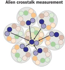
Consider the small cable bundle depicted in the six-around-one cable illustration (page 38). To test and calculate the PSANEXT for the four wire-pairs in the central cable, we need to measure 96 (6x16) pair-to-pair ANEXT combinations. The total test time using the method described above is about 150 seconds, or 2.5 minutes. Let us assume that the total time to test, which includes the time to connect test leads and to upload test results to the PC, is about 6.25 minutes. You will need the same amount of time to make the PSAFEXT measurements for the central cable in this bundle. The total time to certify one link for alien crosstalk compliance in this small bundle equals 12.5 minutes, plus some time to switch the measurement setup for AFEXT. The total test time may, therefore, be estimated at 15 minutes. Using the same assumptions, we would require about 50 minutes to fully test alien crosstalk in one (disturbed) link in a bundle of 24 cables.
Alien crosstalk is going to be a significant performance parameter when transmitting 10GbE over twisted-pair cabling. Therefore, field testing of these performance parameters is required to make sure that the cabling installation can support this high-speed network application. But a reasonable and practical test time is also required, so it is important to devise a sampling technique for selecting a limited number of links to be evaluated and still provide a high confidence factor that the cabling meets the alien-crosstalk requirements.
Alien crosstalk sampling guidelines
Practical field-test results have proven that alien crosstalk between cables in different bundles is non-existent or negligible. These alien crosstalk test methods must also be applied to cabling bundles. To properly test any one “disturbed” or victim link, all of the links that belong to the same bundle of the victim link must be included in the test procedure as disturber links.
Before discussing practical sampling methods to obtain a high confidence in the results, the distinction must be made between the recommendation in the 10GBase-T standard from the IEEE and the developing Augmented Category 6 (Category 6A) cabling standard from the TIA. The test limits in the 10GBase-T standard are based on the signal-to-noise budget for the transmission channel and take into account the insertion loss of the tested link to set the appropriate pass/fail limit values for the alien crosstalk parameters. The test limit values for alien crosstalk in the Category 6A draft standard, however, establish fixed pass/fail limit lines independent of the length or insertion loss of the links involved in the test.
A practical test strategy for alien-crosstalk compliance consists of testing installed links with the highest probability of failing. Compliance with 10GBase-T requirements will be most difficult for the longer links, but if the longest links in an installation pass, all shorter links likely will pass with better margins. Recall that the workmanship of the links in the installation has already been assured by the “in-channel” tests executed to 500 MHz.
Sampling scenario 1: A limited number of links must be certified to support 10GBase-T traffic. You can perform the alien crosstalk tests for those few links, and the following cabling links should be included as disturbers in each of these tests:
· All the links in the same bundle as the selected link;
· Links terminated in adjacent positions in the patch panel.
Sampling scenario 2: A number of bundles in the data center need to be certified for 10GBase-T traffic. Select the longest links. Include in this test sample 2% (longest links) of the total number of cabling links involved or the five longest links, whichever is greater.
When testing for compliance with the Category 6A draft standard, select the longest links in the test sample as well as links with the shortest distance between connectors. Both can be considered the most probable links to fail the transmission requirements. If these links pass, all other less-challenging links will pass the tests.
Industry standards apply
The IEEE project 802.3an document addresses the cabling performance requirements for 10GBase-T, and test methods described in this article fully implement and comply with the 10GBase-T requirements.
The industry will create two different standards: TSB-155 and Addendum 10 to the TIA/EIA-568B.2 standard (see the article by Robert Dennelly, page 28). Why are there two documents? TSB-155 fully specifies the requirements for a cabling link to support the transmission requirements of 10-Gbit/sec Ethernet. The channel specification parallels the requirements established in the IEEE standard. TSB-155 will also include test specifications for the permanent link model. View this document as specifying how Category 6 links can be certified for the 10GBase-T application. Length restrictions will apply for Category 6 links. Although an initial channel limit of 55 meters (180 feet) had been discussed, all Category 6 bundles should be evaluated for compliance. Only after these tests pass do you have the assurance that the cabling can support 10GBase-T.
The second TIA document (Addendum 10) is being prepared to define a new cabling category, called Augmented Category 6 or Category 6A, which offers more performance than Category 6 and is designed to support a 100-meter 10GBase-T channel. Category 6A provides a higher margin above the minimum requirements of 10-Gbit/sec Ethernet for both the alien crosstalk parameters and the performance of the in-channel test parameters above 250 MHz. Specifications for a new cabling type like Category 6A require that performance requirements must be defined for cable, connecting hardware, and patch cords. While the performance limits (pass/fail conditions) for the “channel” are defined and seem to be stable at this time, many more issues must be resolved to complete this standard.
10-Gbit/sec Ethernet is going to be a demanding network technology for twisted-pair cabling. It will require a good Category 6 cabling system that has implemented all of the mitigation measures necessary to limit the impact of alien crosstalk disturbance. Alternatively, this network technology will require the newly proposed Category 6A cabling plant. In either case, workmanship is going to play a significant role in assuring that the installation will support this super-fast new network technology flawlessly.
Field certification of the in-channel requirements and of the alien crosstalk (between-channel) requirements will be the only way to assure that the cabling system will support 10-Gbit/sec Ethernet.HUGO DRAYE is marketing manager, certification tools, with Fluke Networks (www.flukenetworks.com).

