Using an OTDR: How to keep it simple
Not just for use in public networks, the optical time-domain reflectometer no longer has to be an intimidating tool.
by Christain Schillab
Communications networks never go slower, never get simpler, and never stay the same. Likewise, certification testing for fiber-optic cabling has also changed.
New test equipment and enhanced testing regiments help ensure that cabling can support the new demands placed on networks. Born from legacy test equipment for telecommunications networks, some of these fiber testers were difficult to use. But a new generation of fiber test equipment is designed to make it easy to certify fiber to the latest standards.
Not long ago, the state-of-the-art for fiber-optic cabling was the 100Base-FX standard from the Institute of Electrical and Electronics Engineers (IEEE; www.ieee.org), which supported a bit rate of 100 Mbits/sec over a channel with an attenuation of 11 decibels (dB). Today, for IEEE 10GBase-S to support a transmission rate 100x higher than 100Base-FX, the transmission channel must attenuate the light by no more than 2.6 dB. It is this tightening of requirements for the physical media that represents a challenge for all components used to build and test a transmission path.

A standards-compliant connector can contribute up to 0.75 dB (0.5 dB typical) to the total loss. This would mean that if you patch two fiber segments together, there would be a total of four connectors, which could-even though each individual segment is compliant-result in worst-case loss of 3 dB (4 x 0.75). This exceeds the loss budget left for the entire link, and with a negative allowance left for the fiber itself.
More than a loss measurement
It is here where new test methods are required. Installers who work with optical fiber are, no doubt, familiar with the optical loss test set (OLTS). Performing a loss-length test with an OLTS is an essential part of fiber installation. Every link needs to be tested to ensure it is within the loss limits. But an OLTS will only show if a link has passed or failed. If it fails, the OLTS will not show you why it failed, or where.
For these answers, an optical time-domain reflectometer (OTDR) comes into play. Using an OTDR need not be complicated or confusing. Understanding a few basic concepts will make OTDR use as straightforward as using a copper certification tool.
Testing fiber links as defined by national and international standards, such as the TIA/EIA-568-A and ISO-11801 specifications, includes the use of an OLTS. Recently updated standards that focus on test methods for installed fiber links, such as ISO-14763-3 and TIA TSB-140, now recommend the complementary use of an OTDR. These new standards add the use of an OTDR to verify not just that the link has passed, but to ensure the quality of each installed component on the link.
Two levels of testing are defined in these updated standards: Basic (or Tier 1) testing uses an OLTS. Extended (or Tier 2) testing involves the use of an OTDR and an OLTS.
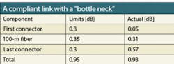
The following example helps demonstrate how an extended test regime can help to ensure consistent quality during installation. Assume that the first connector in a 2-connector, 100-meter fiber link performs extremely well, while the second connector is poorly installed or contaminated. In such a circumstance, the measurement with an OLTS may show that the link passed by a slim margin of 0.02 dB, but does not identify the second connector as a bottleneck (noted in bold).
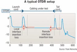
Identifying bottlenecks is the strength of an OTDR, which sends a pulse of light into fiber and measures the light reflected back at each component as the light lost at that component. The same is true for backscattered light along the length of the fiber itself.
Little setup required
An OTDR can produce accurate, highly detailed measurements, if the correct setup and necessary accessories are employed. Recent versions of standards like ISO-14763-3 make an attempt to specify all necessary elements for a correct measurement with an OTDR, eliminating common sources of measurement error, including:
- Specifications for launch and receive fibers;
- Correct use of launch and receive fibers;
- Instructions detailing how to position the cursor for the correct reading of link, component, and segment attenuation;
- List of conditions under which it is vital to measure each fiber in both directions.
You may view these setup requirements as overly complex, which may explain why many consider the OTDR to be a tool for experts only. This is also why installers and contractors may choose not to bid on projects that require an OTDR, or subcontract this work to a company specializing in fiber. Such thinkingis in contrast to the certification of twisted-pair copper cabling systems, where after setting the correct standard, a single press of the autotest button does everything.
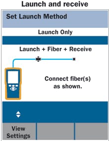
Fortunately, the actual use of the OTDR is not as challenging as it appears. Making sure that test leads, launch fibers, andreceive fibers are in a crisp condition, and are clean and correctly connected, will always be your responsibility. But the remainder of the setup steps can be taken care of by the instrument. Newer OTDRs will create an image of the proper setup configuration. You merely need to make connections and have the instrument “learn” the launch and receive fibers.
After this step, the tester will be ready to certify links and all included components for their compliance. Often, a project-specific standard, which is derived from the manufacturer’s data sheet or reference implementation, will be used to set these limits.
Pass, fail, or squeak by
When the tester is properly configured, the tests are as simple as copper certification. The most common situation should be that the link passes, and a “pass” indication on the summary screen will indicate the tester evaluated all elements of the link. Results are stored for later reporting. The instrument also automatically subtracts the contribution of the launch and receive fibers from the total link, showing only the total overall loss.
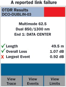
While this example is sufficient information for a passing link, you will need to dig deeper and get more-detailed information if the link (or parts of it) failed the specified limits.
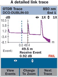
You can see, for example, that the loss may be 1.07 dB and within the limits, but a single bottleneck contributes 0.92 dB to the overall loss.
A fully automatic OTDR automates the test to the same level as a copper field tester, using internal expert diagnostics to interpret all the information from the OTDR test, and presents the results in a simple, easy-to-understand table.
Everyone’s an expert
Many react negatively when they hear the term “OTDR.” But rather than thinking of words such as “complicated” and “expensive,” you could think phrases such as “just like my copper tester,” and “a chance to grow my business.” Installing and testing fiber may be new to some contractors, but the right equipment can make the job easier.
An expert reader of this article will recognize the trace shown in the illustration above. The launch and receive events are clearly visible to the left and to the right of the link. Also visible is the 0.92-dB receive event at 49.5 meters. But the key to today’s OTDRs is that you don’t have to be an expert. If you are an installer of copper cabling systems, an OTDR will offer you three qualities:
1. Expert diagnostics that make the OTDR work much like your familiar copper certification tool;
2. A means of bidding on more jobs, growing your business and increasing profits;
3. The ability to move your knowledge of copper systems into a new area and become a fiber expert.CHRISTIAN SCHILLAB is segment product manager with Fluke Networks, Europe (www.flukenetworks.com).

