Twisted-pair options for 10-Gigabit Ethernet

Conducting appropriate tests will help ensure your medium of choice is ready for high-frequency, high-speed transmission.
Many companies are planning to install networks with the ability to transmit 10-Gbit/sec Ethernet to meet the ever-increasing demand for bandwidth and improved response times. The need for higher bandwidth first manifests itself in the backbone cabling or in data centers. Shielded cabling systems are entering center stage in the promotional battles for market share. The question whether to select, specify, and install unshielded versus shielded has consequently become the topic of the day.
The Institute of Electrical and Electronics Engineers (IEEE; www.ieee.org) completed and approved a new chapter in the Ethernet standard (802.3) to enable 10-Gbit/sec Ethernet transmission over twisted-pair copper cabling. This implementation, called 10GBase-T, is specified in a standard that supports both unshielded twisted-pair (UTP) and screened or fully shielded twisted-pair (STP) cabling systems.
This article explains the transmission-performance requirements for the twisted-pair cabling system defined in the 10GBase-T standard. It will also discuss the following questions:
Twisted-pair transmission requirements
To achieve the 10-Gbit/sec data rate, each wire pair in the twisted-pair cabling must be able to transmit 800 million symbols per second (data rate of 800 Mega Baud). A “symbol” is a voltage level; a new symbol must be transmitted every 1.25 nanoseconds (or 1.25 billionth of a second). To support this very high rate of signal transmission, the cabling performance parameters are specified up to 500 MHz. In comparison, the Category 6 cabling standard defines the transmission performance of the cabling over the frequency range from 1 through 250 MHz.
The cabling standards characterize the performance of twisted-pair data cabling using a signal-to-noise ratio (SNR) analysis. This method defines:
- The minimum required signal strength (or the maximum signal loss allowed) over the frequency range of interest-in this case, over the range 1 through 500 MHz;
- A number of noise parameters or disturbances that cannot exceed established values over the same frequency range. The specified noise parameters are related to crosstalk between wire pairs in the cable and signal reflection on each wire pair measured by the return loss parameter.
Because of the very high frequency range required for 10GBase-T, the crosstalk requirements must be expanded to include not only the crosstalk that happens between wire pairs within each cabling link, but also to include the crosstalk that is induced from wire pairs in adjacent cabling links. The latter is called alien crosstalk. The performance of each individual cabling link is certified by the “in-channel” tests, while the alien crosstalk performance or the coupling between wire pairs in adjacent links is to be certified by the “between-channel” test parameters.
How can you be assured that the installed cabling system will support 10GBase-T transmission? Industry standards define the test parameters as well as the measurement methodology to assure compliance of installed cabling systems. This testing procedure is called cabling certification.
Applying the standards
The IEEE has been the organization to develop, expand, and maintain the “Ethernet” standards, in its 802.3 set of specifications. IEEE project 802.3an developed and defined the system to transmit 10-GbE over twisted-pair cabling. This project encompasses all aspects of the network implementation, including the minimum capability of the cabling link between a transmitting device and a receiving device. The IEEE is focused on the transmission performance of the end-to-end cabling link independent of the number of connections or other cabling installation issues. IEEE 802.3an development has been completed and was approved by it standards board in June 2006.
The cabling industry is undertaking two sets of activities:
- Guidelines for cabling compliance with the transmission requirements of 10GBase-T;
- A new cabling standard that delivers better transmission performance than Category 6, called Augmented Category 6 (Category 6A) or Augmented Class E (abbreviated Class EA by the International Organization for Standardization [ISO]).
In the North American market, the Telecommunications Industry Association (TIA; www.tiaonline.org) is the leading standards body for data communications cabling. The ISO, meanwhile, develops, publishes, and maintains standards for the worldwide market. Both standards bodies are involved with the two activities mentioned above.
Cabling guidelines for compliance with 10GBase-T
The TIA published a document titled Telecommunications Systems Bulletin 155 (TIA TSB-155), which contains the guidelines and performance criteria by which any cabling system can be evaluated for compliance with the cabling transmission requirements for 10GBase-T. The guidelines in TSB-155 address the in-channel performance (test parameters that define the performance of an individual cabling link over the frequency range from 1 through 500 MHz) and the between-channel performance (signal coupling between adjacent links commonly referred to as alien crosstalk). The ISO is in the process of creating a Technical Report (TR 24750) that serves the same purpose, and intends to provide the same guidance as the TIA TSB-155 document. (These guidelines do not suppose a specific Category or Class of cabling, but it will be difficult to meet the performance established by TSB-155 [TR 24750] for any cabling lower than Category 6 or Class E.)
New cabling standards
Both TIA and ISO are developing a new cabling type called Augmented Category 6 (Category 6A) or Augmented Class E (Class EA). This new cabling will offer better performance than Category 6 or Class E cabling. The performance of the in-channel and between-channel parameters will be defined up to 500 MHz. The standards activities that define the Augmented cabling systems are not yet complete, even though many manufacturers offer Category 6A (Class EA) solutions in the market. The TIA development is further along than the ISO development, and will be published as Addendum 10 to the TIA standard 568-B.2 (TIA-568-B.2-10). This TIA document is, at the time of this writing, in Draft 7.0.
An important reason for the new cabling systems is that Category 6 cabling may not satisfy the between-channel performance (alien crosstalk performance), especially for longer links. TSB-155 states that Category 6 “should” perform satisfactorily for links up to 37 meters long; it may well work up to 55 meters, and it may need some mitigation if you want to run 10GBase-T over Category 6 links longer than 55 meters.
In a real-world installation, the alien crosstalk performance of installed Category 6 cabling depends on many factors. The best advice we can give: Test alien crosstalk performance of installed Category 6 cabling before deploying 10GBase-T. If the links pass the requirements specified in TSB-155, they are ready to support 10GBase-T. One design goal for the Category 6A system states that it shall satisfy the alien crosstalk performance for 10GBase-T for a full 100-meter horizontal channel.
Starting from scratch
A new cabling installation should be treated as a long-term investment. Electronic devices are typically replaced several times within the lifespan of the cabling system. Replacing a cabling system is a much more disruptive and costly project than exchanging network devices like switches and routers. You should, therefore, consider the best cabling system for the time horizon of your investment. In a new data center design, this decision should favor a Category 6A cabling system.
As mentioned earlier, shielded cabling types are getting much attention in the Category 6A market. The standards do not favor UTP over STP construction. Instead, as was explained earlier, the standards set performance limits for the in-channel transmission capability as well as for the between-channel capability.
We have witnessed the testing of many UTP cabling installations that fully meet the requirements spelled out in the proposed Category 6A standard. The shielding in the screened cable types offer better electromagnetic interference (EMI) performance and diminishes the signal coupling between wire pairs in adjacent cabling links. A shielded cabling installation, if properly installed, should offer better margins for the alien crosstalk tests.
This raises an interesting question: Do cabling systems with very good margins (15 dB or more) perform better in everyday network operations than cabling with merely good (say, 5 dB) margins? We believe the answer is, “No.” The distinction is not noticeable. It is true that a reasonable margin of a few dB above the minimum requirements protects network traffic from spurious and random EMI events that undoubtedly occur. Also, remember that the dB scale is not a linear scale. For example, a worst-case alien crosstalk margin of 6 dB means that at the worst-performing frequency, the measured alien crosstalk signal is half of the allowable signal level for alien crosstalk.
Considering unshielded
In the selection process between unshielded and a variety of screened and shielded cabling options, UTP remains the more economical system. Installation contractors in the North American market are familiar with unshielded cable types. Category 6A UTP may, however, bring a few new challenges.
Many of the Category 6A UTP implementations have bigger outside diameters, and the density in patch panels has decreased. The increased outside diameter (OD) creates a greater distance between wire pairs in adjacent links, thereby reducing the between-channel signal coupling. A bigger OD for the cabling does, however, affect the fill rate in ducts and pathways. An increase in the OD of 0.1 inch, from 0.25 inch to 0.35 inch, represents an increase in fill volume of 21%. It also affects the ease of handling and bending of cable bundles. If you select a UTP Category 6A cable with an increased outside diameter, pathway layout, duct sizes, and cable suspension should be designed to accommodate the OD parameter of the cable.
Alien near-end crosstalk (NEXT) is susceptible to the performance of the cabling near ends of the link, most noticeably in patch cords, patch panels, and the wire management in the racks. To alleviate or mitigate alien crosstalk problems in UTP installations, the Category 6A patch panels support less density and trade off that density for alien crosstalk performance by allowing more space between jacks in the panel.
Alien NEXT for UTP cabling can also be improved by adjusting the practices of bundling in the wire management of the racks. Allowing more free flow between the cables and placing wraps or hook-and-loop ties a few feet apart, rather than a few inches apart, will help. Also, smaller bundles are more manageable and will require less time to conduct the alien crosstalk tests.
Shielded/screened options
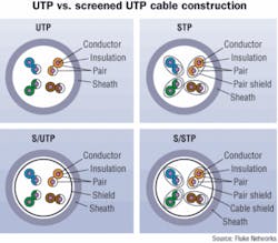
It is important to note that there are several different varieties of shielded cabling, and that a series of new acronyms has emerged to describe the different cable types. In the most common construction type, the wire pairs are fully covered with a metal foil. This construction used to be called FTP (foiled twisted-pair) or ScTP (screened twisted-pair) but is now often referred to as F/UTP (foiled/unshielded twisted-pair) or S/UTP (screened/unshielded twisted-pair). An alternate construction provides a foil around each individual wire pair. And the Category 7 cable construction provides a foil around each wire pair, then a foil around the four foil-screened wire pairs and lastly, a braided screen woven of thin wire around that outside foil. This cable construction is also called SSTP (shielded screened twisted-pair). The flexibility and manageability of SSTP is much less than that of UTP.
The foil screen or shielding is effective in preventing high-frequency signal interference between wire pairs in adjacent cables. Good cable balance offers great immunity from interference caused by lower-frequency signals. To obtain these benefits from screens, you must follow a number of very important installation practices. The key concerns are the shield must fully surround the wire pairs in the cable from end to end, and must provide proper grounding.
The shield must be kept intact over the entire length of the cable, and must fully surround the cable and connecting hardware. If the shield is, for example, formed into a pigtail over the last inch of the cable, it will reduce the protection against EMI and alien crosstalk. In addition, avoid splitting the shield at sharp bends in the cable. The shield is typically a ribbon of aluminum foil that is wrapped around the cable. If the cable is bent at too sharp of a radius, the shield may separate, thereby reducing the effectiveness of the shield and its ability to protect against alien crosstalk.
The shield must be grounded on both ends of the link. It is often said that a shield is 90% effective when it is grounded at one end of the link. Such a shield continues to protect the wire pairs against many external high-frequency disturbances, but an open-ended shield may allow resonances at certain frequencies. A resonance creates the chance that the signals couple into the data wire pairs, creating a significant alien crosstalk disturbance at those individual frequencies. Field certification may record very low margins for alien crosstalk at those frequencies.
Because the shield should be terminated to ground at both ends, it is critical that the ground potential at both ends is approximately the same to avoid any ground-loop currents. The TIA-607 standard on grounding and bonding allows a maximum difference in ground potential of 1 Vrms (Volt root mean square) between the two ends. This rule requires that the telecommunications system is grounded throughout in compliance with the TIA-607 standard and that the electrical system in the building is correctly grounded and fully complies with rules spelled out in the National Electrical Code and other codes enforced by local jurisdictions.
In the field, you can verify that the ground potential meets the difference requirement before you connect the other end. Connect the shield at one end, then measure the alternating-current voltage between the shield and the ground connection at the other end using a digital voltmeter that covers a bandwidth of 100 kHz or better.
The performance in or near the patch panels plays a significant role in maintaining the effectiveness and protection delivered by a shielded cable. Installation workmanship and experience play a big role in the quality of the installed system. Field certification verifies that the desired quality has been delivered.
Shielded cabling may also require additional testing in Power over Ethernet (PoE) applications because the shielding tends to retain heat within the cable, which increases return loss and reduces cable life. The proposed 802.3at standard, which increases the maximum PoE power from 13 watts to 30 watts, makes this issue more critical. 802.3at will set maximum temperature limits for unshielded cabling but does not yet address shielded cabling.
Because PoE is not often used within data centers, the use of shielded cabling in the data center sidesteps this potential problem. If PoE is run over shielded cabling, the cable should be tested periodically for return loss to assess whether any thermal damage may have occurred.
Shielding against aliens
The IEEE 10GBase-T standard includes requirements for cabling; the TIA TSB-155 and ISO TR 24750 documents incorporate these requirements. The new cabling standards under development-Category 6A and Class EA-aim to deliver a future-ready cabling system that supports the full 100-meter channel requirements for 10GBase-T. These new standards also aim to support possible future developments.
We can predict that alien crosstalk performance is going to be part of any future high-speed network application. Because of the emphasis on alien crosstalk, screened/shielded cabling types are gaining attention in the market. Properly installed shielding enhances EMI performance in general and alien crosstalk performance in particular.
Certification testing has always been an important part of cabling deployment. It becomes a very important step if you are interested in deploying 10GBase-T over installed twisted-pair cabling. Certification of new Augmented cabling systems, whether constructed with unshielded or shielded components, delivers the assurance that the cable system is ready to support 10GBase-T and beyond. In-channel testing should be performed on 100% of the links, and alien crosstalk testing should be performed on a selected number of disturbed cables in the cabling installation.

