Cable planning for IP convergence

Understanding the art and science of building structured cabling systems for digital security applications.
by Carol Everett Oliver
There are two mindsets concerning Internet Protocol (IP) convergence: One is, “IP network video is here now,” and the other is, “IP is a long, long way away.”
But the bigger question is not “when?” but “how?” Who’s in charge here, and what steps need to be taken now to futureproof the cable plant and telecom rooms (TRs)?
Information technology (IT) managers may feel like their networks are at risk, and security integrators may feel that their environments and customer bases are threatened; however, those who are accepting that closed-circuit television (CCTV), access control and,eventually, other building automation systems (BAS) applications will eventually reside on an Ethernet-based network will benefit by working together.
Both parties bring separate values to the table. IT integrators know about voice and data infrastructure, industry standards, routing, switching and network-storage capabilities. Security integrators know cameras, transmission, video storage and physical risk assessment. In addition, facilities managers or mechanical engineers know power demands and heating/ventilation/air-conditioning (HVAC) systems.
It all starts with a collaborative plan to combinedata, voice, video and BAS into one integrated network solution. Whether these systems will run in parallel and bridge with a common backbone or will be integrated into both the backbone and horizontal cabling, the infrastructure will need to be consistent to provide the most return-on-investment.
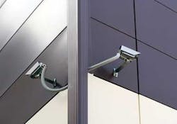
CCTV meets structured cabling
Historically, legacy security and building automation systems operated over their own proprietary physical cabling and software control programs. “When it comes to legacy CCTV, there are truly no cabling standards,” states Richard Caesar, director of global engineering for SST (1sst.com), a national security integration company. “It could be coax cable and separate power cables running analog cameras in a legacy layout; it could be IP over UTP with PoE or a combo of UTP and fiber and media converters; it could be analog cameras with coax andbaluns running through an Ethernet switch for structured cabling; or it could even be wireless.”
Caesar adds, “In addition, there were no standards for distances as it was dependent on the camera, or we could just throw an amplifier on the cable and push it out to a mile.”
For many years, video “surveillance” was accomplished by simply installing an analog (CCTV) camera and attaching it through coaxial cable at each camera location, then connecting it to a VCR and a monitor. This system relied upon human observers, normally watching multiple screens to trigger any type of response. In other scenarios, the system was set up with no observer at all, but was designed to record what happened over a certainperiod of time. This type of system allowed for event “forensics,” enabling research into an event after it had occurred (mainly for identification).
But there has been a shift to have all of these functionsinterconnected. The goal of today’s integrated securitysystems is to combine data, video, and analytics in new ways that allow for a more proactive response. “As all building applications begin to converge on a common cabling platform,” Caesar explains, “all systems will ride on an Ethernet-based network, also known as ‘browser based,’ where all system components communicate—just like phone and computers coexisting on today’s IT network.”
The path to IP
IP convergence for these previously proprietary, non-standardized devices can be achieved through structured cabling. Digital IP-based cameras, as well as legacy analog cameras, can be connected through an Ethernet-based switch and then to digital network storage devices to allow real-time event recognition and alarm generation.
IP convergence also means that the cable media will either be UTP or fiber versus coaxial. Moving to a UTP-or fiber-based media will save on pathway space as well as material and installation time and costs, because it will be the same cable type that supports data and voice applications. Also, deploying a structured cabling layout for CCTV will allow other devices, such as access control, to easily attach to this network now or in the future.
There are three basic scenarios for CCTV over structured cabling as it shifts from a legacy architecture to total IP: Analog, hybrid and total IP.
Coax-based analog cameras can be cabled through structured cabling. A balun needs to be placed from the cable connection on the back of the camera to convert a 75-¿ unbalanced signal of coaxial to a 100-watt balanced signal of UTP, which is then terminated into a workstation outlet. Just like voice and data ports in the TR, the UTP cable for the cameras are terminated into patch panels, which connect to a switch and then to the digital video recorder (DVR). At the DVR, a balun isinserted to convert the video signal back into analog.
When combining analog and digital cameras into one structured cabling system, there is a mixture of termination equipment. This hybrid scenario will be most often found in facilities that are upgrading and will be adding IP cameras to their existing analog installed base.
It’s simple to add an IP camera to an existing analog system that is already cabled through UTP to the TR. Most IP cameras have an RJ-45 connection, allowing a patch cord to plug into the outlet. From there, it follows the structured cabling guidelines with UTP cable terminating into a patch panel in the TR, which is connected to the switch, allowing both the analog camera and IP camera to reside on the same network. Both cameras can attach to a server, such as an IP-enabled DVR.
The third and last step on the path to IP is a total IP camera scenario. Its biggest benefit is that it allows total remote accessibility from web-enabled devices. A total IP CCTV solution emulates the cabling architecture of data and voice applications. IP cameras can also be powered through the unused pairs of the UTP cable via a midspan or endspan injector to provide PoE. This eliminates the need for a power outlet directly at the camera location, and simplifies moves, adds and changes.
Sometimes, the 100-meter (328-foot) limitations of UTPcable in an Ethernet-based network (per TIA/EIA-568-B standards) pose a hurdle when trying to monitor the many outreach locations. Fiber-optic cable will allow for cable runs of more than 5,000 feet on multimode and more than six miles onsinglemode cable. Fiber is also smaller in size, has bettertensile strength, is immune to electrical interferences, provides the highest bandwidth, and a higher degree of securitybecause it is difficult to tap into. But just like the media conversion that occurs through baluns when using analogcameras over UTP cabling, fiber-optic cable will need to be converted to copper for connectivity into the DVR or server. In this scenario, media transceivers are required.
Planning ahead
Migrating from a separate proprietary analog system in CCTV to a total structured cabling system should make it easier to plan combined pathways and TRs alongside the data and voice network, but additional termination equipment will need to be factored into the design.
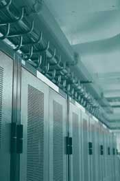
When planning for the size and location of the TR,several critical design decisions must be made. For example, is the termination field going to be mounted on the wall or in a rack? Most CCTV equipment is rack-mountable, which makes it easier to plan how many racks or cabinets you needdedicated for your security components. The number of cameras, as well as room location, could also help determine your selection of a full-size rack, which would be located in a securely locked room or a lockable cabinet. Racks can alsobe equipped with lockable enclosures for added safety, and equipment such as the switches and patch panels and hubs.
Another main concern with the TR is making sure that it is kept at a consistently cool temperature and that there is proper airflow to eliminate the danger of any equipment overheating or subsequent shutdown. BICSI (www.bicsi.org) recommends keeping the room at 64° to 75º F when there is active equipment. Active equipment and power distribution units (PDUs) generate significant heat, with active equipment generating more than PDUs; however, one or two servers do not generate enough heat for an additional air conditioning unit. And most high-density storage equipment should be located in the main crossconnect or data center. It is wise to use the expertise of a mechanical engineer to provide a proper HVAC system and to figure out the total British Thermal Units (BTUs) that will be generated from any equipment, and to assure the room size will accommodate the airflow needed.
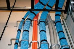
Network video can connect to a wide area network (WAN) via the existing voice and data fiber backbone, if there are spare fibers. More often than not, excess strands of the fiber-optic cables specified for the data and voice network sit unterminated for future applications. When backbone cabling for data and voice is installed, there is usually a 24- or 48-strand multimode fiber to each TR for LAN and WAN connection. Practically, however, usually only half of those strands get lit. So, video becomes the “future application,” and can use the available strands.
For the horizontal infrastructure, most IT managers opt to run a parallel or subnet infrastructure dedicated to CCTV rather than use the same termination equipment (patchpanels, switches, etc.) as the data and voice. Therefore, aparallel system would mirror the data and voice infrastructure, with just a few added components.
Room planning
When planning a telecom room for data and voice, the following components are configured into the design by the cabledesigner and IT personnel:
- Physical support (racks, cable tray);
- Cable and cable management (UTP or fiber);
- Patch panels;
- PoE;
- Ethernet switch/router/hub;
- PDUs;
- HVAC.
Whether your cameras are analog or IP will determine which components you will need to install in the TR. And, the number of cameras to be terminated in the TR will determine the number of additional separate racks and cabinets. This is the tricky part, as each vertical market will have different requirements for the number of cameras as well as the location.
Here is a generic product and size guide for a 16-channel camera and DVR capacity:
- 19” rack (45U) or cabinet (11U);
- Server (DVR) (4 to 5U);
- Hub/transceiver (1U);
- Monitor (6U);
- Media converter (0U);
- Router/bridge (1 to 2U);
- Ethernet switch (1U) in a lockable enclosure;
- 24-port patch panel (1U);
- PoE midspan injector (1U).
BICSI has a formula to determine how large a TR should be based on the square footage of the area served. In anenterprise situation, it is easy to plan how many data and voice drops you will need. But trying to figure out how manycamera locations and, subsequently, additional cable- management racks and equipment per square footage or per building, is not simple.
The number of cameras will be dependent on the business model or vertical market. For example, a 4U or 5U DVR can serve 16 cameras, which is probably more than what you would need for one floor in an office environment . But for a casino or bank, you would probably need five or more times as many cameras, which will then affect the space allotted for termination equipment in the TRs.
Each vertical market will have its own equipment and special demands. Therefore, there is no standard formula for figuring out how many additional racks are needed for video, because it will be based on the number of camera locations served by each TR.
Previously, security was an afterthought, so allotting space for the equipment and monitors was often relegated to housing venues, such as broom or utility closets. Today, a cost-effective, integrated IP-based network will require that all applications reside in the same TR.
Cross-training for the future
Pre-planning a TR is critical to the reliability of the IP security system, as well as the ability to add future applications. But while the telecom cable planning and management responsibility falls under the helm of the IT manager, it isimportant to glean the knowledge of security professionals to aid in your planning.
By 2010, the cable media mix will shift to a majority of UTP (50%) and fiber (31%), with coaxial declining to 19%, according to FTM Consulting (ftmconsultinginc.com). Additionally, more than 50% of the video surveillance market will be IP-based. This migration, or “path to IP” will be an evolution, leaving time for IT and security integrators to become cross-trained to provide end users with the right tools and practices to be ready for the next application convergence.
CAROL EVERETT OLIVER, RCDD, is marketing analyst with Berk-Tek, a Nexans Company (www.berktek.com).

