by Betsy Ziobron
Improvements have advanced the ubiquitous interface from Category 3 to today's Category 6A, and innovation designs go even further.
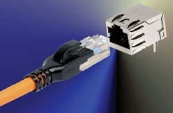
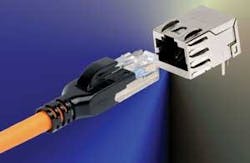
The twisted-pair connector interface, often referred to as an RJ-45, is an 8-position, 8-contact (8P8C) modular plug and jack that was originally patented in 1975 by Western Electric Company, the manufacturing arm of AT&T. Since that time, many technological improvements have overcome crosstalk as data rates have evolved from 16 MHz for Category 3 to 500 MHz for the latest Category 6A standard.
Many in the industry believe 500 MHz to be the last "hurrah" for the unshielded version of the 8P8C connector, while shielded versions are undergoing innovative development to support Category 7 and 7A performance up to 600 MHz and 1000 MHz, respectively. But others are not quite ready to close the book on UTP.
Split compensation
When the 8P8C connector was introduced, the pin-pair assignment maintained Pair 1 on the two middle Pins 4 and 5, and Pair 3 was split around Pair 1 onto Pins 3 and 6. The reason for the split pair was to maximize the mechanical compatibility of the connector with existing one-pair analog telephones. Required by FCC specifications, this wiring scheme made sense at the time but has since been the source of challenge. With one pair split around another, the coupling from Pins 4 and 5 onto 3 and 6 introduces the most crosstalk within the interface.
"When the main application was just voice, and the frequencies of interest were in the single digit kilohertz, the connector was electrically invisible, and the split pair was a non-issue," says Luc Adriaenssens, vice president of research and development for CommScope (www.commscope.com). "As we progressed to higher data rates, it became more apparent that the split pair caused electrical problems, and that challenge has stuck with usover the years. The advantages of backwards compatibility are so compelling, however, that a lot of creative people in the industry have worked to solve the problem."
Electrical requirements for the 8P8C connector were introduced with the Category 3 standard, when manufacturers had to start paying attention to tolerances. "If you take apart a Category 3 connector, it's a very primitive lead-frame design with eight contacts coming from the IDC towers on the back to the front of the jack where they make contact with the plug," explains Asef Baddar, manager of applications engineering for Leviton (www.leviton.com). "At that time, there weren't many requirements, but when we moved to Category 5, the basic lead-frame design just wasn't going to cut it, and it was time to look at other options."
Crosstalk in the plug-jack interface became a concern, with performance characteristics for Category 5 specified for frequencies up to 100 MHz. To reduce the crosstalk, manufacturers began using compensation techniques, such as twists within the jack.
CommScope's Adriaenssens recalls deploying a crossover technology where the conductors located close together were crossed to add opposite polarity of the offending crosstalk that occurs in the plug: "Initially, we didn't have to cross over all four pairs. Over time, the engineers in the industry got very clever in determining where to put in twists and, eventu-ally, little extensions were added to situate conductorscloser together without physically having to cross them over. There were various techniques deployed among manufacturers, but all focused on compensating for crosstalk, with the split pair being the worst."
When Category 6 was introduced with performance frequencies up to 250 MHz, more sophisticated techniques were required to compensate for crosstalk. Workingwithin the same footprint, manufacturers added a small printed circuit board between the IDC contacts and the pins in the front of the jack.
"The circuit board included capacitors that further compensated for the crosstalk, and it was a significant innovation that allowed us to make a better performing jack," says Baddar. "Adding the circuit board to the jack added cost—it was a completely new process that required modifying the manufacturing process as we knew it."
Today, most Category 6 and some Category 5e jacks include a circuit board, as it was the most cost-effective and sophisticated method of adding crosstalk compensation. "A circuit board allows manufacturers to make minor modificationsand fine-tune the performance by easily changing the layout of the traces," says Adriaenssens.
A significant achievement
Over the past few years, the need to increase data rates has further increased the operating frequencies, and now Category 6A specifies performance up to 500 MHz to support10GBase-T. To mitigate alien crosstalk that occurs betweentwo adjacent unshielded connectors, manufacturers havedeployed a variety of techniques that include partial shielding, physical space, and repositioning of the IDC towers.Enhancements to the printed circuit board within the jack were also required. Others turned to the fully shielded version of the twisted-pair connector interface.
According to Tom Williams, RCDD, director of datacomm with BTR Netcom (www.btr-netcom.com), how and where the actual contacts are positioned onto the circuit board became very critical with Category 6A unshielded jacks. "The quality of the manufacturing for Category 6A has stepped up to a whole new level of precision," he says. "That is why most UTP vendors have not been able to develop a component-rated jack, which is different than a channel-rated jack."
On the other hand, some vendors offully shielded solutions, like BTR Net-com, required no additional engineering within the jack to meet the requirements of a Category 6A system, with additional headroom to boot. This has led many to believe that Category 6A is truly the last "hurrah" for UTP.
"There are those that still believe UTP is better, but I don't believe they're going to have a choice once we move beyond 10 Gig," says Williams. "I'm confident that copper will ultimately support 40 Gig, and possibly 100 Gig at shorter lengths, but it will have to be shielded."
Others remain optimistic about UTP's future. "Theargument that shielding will be required for anything above500 MHz is the same argument that has taken place over the past two decades as we moved from 60-meg Token Ring to10 Gigabit Ethernet," says CommScope's Adriaenssens. "We've proved that wrong time and time again. With all the momentum and clever people behind UTP, I wouldn't bet against it."
John Siemon, vice president of engineering for Siemon(www.siemon.com), says, "Without a doubt, the most signifi-cant accomplishment of the twisted-pair connector inter-face over the past five years is its ability to support networks operating at 10Gbits/sec. As an engineer, it's difficult toaccept a hard stop for any technology, but I do not foresee a high return on development of UTP beyond 500 MHz when there are other cost-effective, lower-risk options available.
Siemon adds, "Shielded twisted-pair is the logical choice because it provides significantly higher channel capacity than UTP over the same frequency range, with the potential to go even higher. But given unlimited time, funding, andresources, almost anything is possible."
Siemon points out that the complexity required to support the full range of twisted-pair implementations for10GBase-T has resulted in significantly higher latency andpower consumption than 1000Base-T. "These factors point to the need for further optimization of electronics and cabling to support this application," he says.
In fact, many UTP vendors are still devoting plenty of R&D to further optimizing the unshielded twisted-pair interface. "Our focus is on continuing to improve the Category 6Aunshielded interface and the cabling," says Adriaenssens. "We're not just looking at megahertz and performance, butalso making sure the reliability of the connector is not com-promised as you put different applications onto the circuit, such as Power over Ethernet."
A step further
While no one knows for sure whether Category 6A is the stopping point for the unshielded twisted-pair connectorinterface, it's become apparent that the shielded version isprevailing beyond 500 MHz. Already, shielded twisted-pair connectors on the market meet the IEC 60603-7-7 standard for Category 7 performance up to 600 MHz and the soon-to-be-ratified Category 7A standard for increased frequency up to1000 MHz. In fact, some of these connectors were devel-oped before Category 6A.
"To support frequencies above 500 MHz, ISO/IEC has specified interfaces for Category 7A and Class FA that separate the pairs into four separate quadrants," notes Siemon. "These designs readily connect to cables that have individually screened pairs to elevate crosstalk performance of cabling links and channels by more than 20 dB—a 10x improvement."
He adds, "With these designs, return loss is key to extending the bandwidth of twisted-pair cabling beyond 1000 MHz. Balance and noise immunity are also important considerations, and these challenges are solved by adopting connector designs that emulate the performance of the cable towhich they connect."
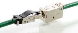
One example of a shielded twisted-pair connector supporting the proposed Category 7A standard is Siemon's TERA connector that terminates fully shieldedCategory 7A cables. "The TERA connector was the first internationally standardized balanced cabling interface to support requirements up to 1200 MHz," says Siemon. "The footprint for the TERA interface was designed to fitwithin the same IEC standard panel opening as that specified for IEC 60603-7-compliant outlets. They are side-stackable and mount directly intoall of the same faceplates and panels used for our RJ-based outlet designs."
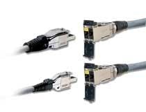
Nexans' GG45 connector, for use with the fully shielded LANmark-7A cabling system, also meets the proposed Category 7A standard. While this connector is another example of one that separates the pairs into four quadrants to overcome the problem of the split pair, it is also backwards compatible with conventional 8P8C modular connectivity.
"The GG45 actually contains 12 contacts; it looks just like the existing interface, but we've added four more contacts to the jack as an alternative to the split pairs," says Dave Hess, technical manager for Nexans (www.nexans.com). "An existing Category 6 or 6A plug uses the original split pairs, and the eight contacts across the top. A Category 7 or 7A plug no longer uses the split pairs but instead uses the eight contacts located in the four corners. The higher speed plug has a protrusion that activates a switch within the jack to make the change."
According to Hess, the key advantage of the GG45 interface is the ability to have a low-cost 10G channel with plenty of headroom combined with the ability to migrate to high-speed 40 Gig using Category 7A patch cords. "A network can be wired up with the GG45 and LANmark-7A cabling system and use Category 6A plugs for the first few years," he says. "When equipment comes out with the Category 7A interface, the system can be easily upgraded by using Category 7A patch cords that activate the switch in the jack."
Like the GG45 and TERA connectors, Bel Stewart's ARJ45 also has the pair contacts located in four quadrants to provide enhanced crosstalk performance. The ARJ45 is compatible with Nexans' GG45 interface; however, it does not include the original Pins 3 to 6 for backwards compatibility with Category 6A plugs.
"The key difference between the ARJ45 and the GG45 is the lack of the switching mechanism in the jack," says Derek Imschweiler, product manager for Bel Stewart (www.belstewart.com). "We didn't add a switch because it makes the connector more complicated and costly, and most of our business is in the active equipment market and not the wall outlet application where backwards compatibility is more advantageous."
Outlook is good
Shielded solutions are growing in popularity, and Category 7A systems are already being installed in specialtyapplications in the U.S.—more predominantly overseas where fully shielded cabling systems have been deployed for decades. While a fully shielded Category 7A solution currently carries a higher material and installation cost, Nexans' Hess points out that it has the potential to provide significant cost savings: "A shielded solution like Category 7A can enable reduced power and crosstalk cancellation at the switch level to poten-tially lower the cost of the equipment; however, we don't see the savings yet because there are no applications calling for this type of performance."
Siemon agrees: "It is true that cabling solutions that offer superior higher noise immunity can enable equipment to operate with less dependence on digital signal processing, and that fewer transistors translate to lower power. Higher performance cabling, therefore, has the potential to reduce power and issues associated with heat management in data centers." Consequently,says Siemon, operating costs could be lower with Category 7 or 7A, or a higher performance Category 6A screened solution than for minimally compliant Category 6A UTP. "The potential cost savings is not fully understood," he says, "but is an opportunity that the IT industry would do well to exploit."
Innovation and investment
Siemon concludes, "For the ubiquitous twisted-pair connector, the primary challenge is crosstalk—especially in association with the nested pairs on Pins 3 to 6; however, the rate of innovation and investment in research has not slowed. Development aimed to further elevate performance of this interface while improving the speed and consistency of field terminations will continue to produce new designs and generate excitement about the point to which the original "RJ" plug and outlet have evolved."
BETSY ZIOBRON is a freelance writer and regular contributor to Cabling Installation & Maintenance. She can be reached at: [email protected]


