Practical deployment and management of InfiniBand
This high-speed interconnect technology requires careful routing and organization of a variety of cabling types, as well as the need to head off cable congestion and air flow restrictions.
by Robert Elliot
High performance computing (HPC) clusters are increasingly being adopted into enterprise data centers to meet the needs of advanced applications. Financial, healthcare, and scientific organizations need the significant power of a clustered server environment, combined with specialized interconnect solutions, to process complex application data quickly and without error.
One solution that is receiving increasing interest isInfiniBand, whose scalable, high-speed interconnect, and extremely low latency have helped it capture significant market share over the past several years. InfiniBand isincreasingly used alongside virtualization technologiesto coordinate server resources and maximize pro-cessing capability and server/storage efficiency.
Installation challenges
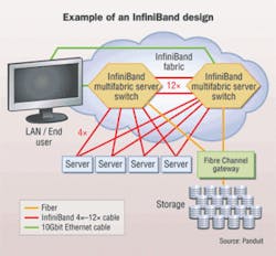
InfiniBand was designed as an open interconnect standard for moving high volumes of data quickly between processors and I/O devices, and has broad industry support. It can work with conventional switches as a pure server interconnect, and with multifabric serverswitches to combine the server interconnect function with Ethernet and Fibre Channel gateways (see figure, "Example of an InfiniBand design").

Data center installers are increasingly called upon to deploy InfiniBand solutions alongside Ethernet andFibre Channel links, and it can be a challenge to routeand manage all cabling types. First of all, InfiniBandcables and connectors are constructed differently than typical Ethernet systems, and are arranged in point-to-point topologies. In addition, InfiniBand solutionsrequire careful management to avoid cable congestionand air flow restrictions that can be created in high-density server cluster applications.
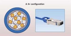
Standard InfiniBand 4X copper cable assemblies are comprised of eight shielded pairs (or four lanes) of 100-¿ impedance twin-axial cable (i.e., twinax), which differs from twisted pair copper used in Ethernetapplications in that pairs of insulated conductors are laid side-by-side and enclosed in a foil shield. The InfiniBand connector is based on a precision screened and balanced edge card design supporting eight differential pairs, and is termed the 4X MicroGiGaCN connector (see figure, "A 4X configuration"). Thesecable assemblies operate in dual simplex (simultaneousbi-directional) mode, where one send and one receive run in each lane support data independently.
The InfiniBand standard supports single data rate (SDR) signaling at a basic rate of 2.5 Gbits/sec per lane to allowa raw data rate of 10 Gbits/sec over 4X cables (the most common InfiniBand cable type used). Double data rate (DDR) and quad data rate (QDR) signaling permit single lanes to be scaled up to 5 Gbits/sec and 10 Gbits/sec per lane, respectively, for a potential maximum data rate of40 Gbits/sec over 4X and 120 Gbits/sec over 12X cables.
By incorporating remote direct memory addressing(RDMA) technology, InfiniBand typically achieves a lowlatency of 3 to 5 microseconds, with some manufacturers claiming latencies as low as 1 to 2 microseconds (in contrast, Ethernet latencies typically range from 20 to 80 microseconds). These features make InfiniBand especially useful as a computing cluster interconnect, since tightly coupled cluster applications require low latencies for optimum performance.
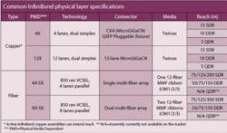
InfiniBand copper cable length is influenced primarily by signal attenuation effects that are magnified at higher data rates. In general, lower gauge wires (i.e., thicker conductors) are used to partially compensate for the higher attenuation. The thickest conductors commonly used are 24-gauge, which result in a reach of approximately 15 meters (50 feet) for standard passive 4X InfiniBand cables operating at 10 Gbits/sec SDR (see table, "Common InfiniBand physical layer specifications").
Cables to be used over shorter distances can be manufactured with thinner wires; 28-gauge conductors are often used for lengths up to 5 meters, and 30-gauge conductors are used in cable lengths of 1 to 3 meters. These thinner cables feature a smaller bend radius for improved cable management. For longer distances, active circuitry located within the connector can be used to extend the length of thicker-gauge cables by up to three times (approximately 30 to 40 meters in the case of SDR), as well as improve overall link margin.
Because of this flexibility, the form factor of InfiniBand cables can vary based on application-specific requirements. Thicker conductors used on standard InfiniBand copperassemblies, however, generally result in a larger diameterthan Ethernet Category 5e or 6 cabling, but offer a greater stiffness and resiliency as well as a larger bend radius thanthinner diameter types.
Fiber InfiniBand cables can be deployed in situations where extended-reach solutions are required. Fiber cable assemblies have a smaller diameter and bend radius than copper twinax, which canoffer routing and management benefits in tight data center spaces. In practice, however, a balance of short reach applications and cost considerations has helped copper twinax evolve into the preferred medium for InfiniBand deployments. The distance between switches and servers in cluster applications rarely |exceeds 15 meters, and active copper assemblies can typically extend the reach of copper cables beyond that length.
Cluster architectures are characterized as having a large number of commodity servers connected to a fabric of network switches that control the flow of information as the job progresses. Cable management is a central issue in these dense environments, where large diameter, short-reach InfiniBand assemblies must compete for space with other network components and cabling.
InfiniBand cable management best practices can be broken down into two areas:
• Horizontal routing and support. The first location to consider when deploying InfiniBand assemblies is at the point of connection to active equipment ports. Conventional InfiniBand CX4 connectors are significantly larger (typically 1.1" x 0.65") than familiar RJ-45 connectors (typically 0.46" x 0.37"). Also, cables are heavier (0.22 lbs. per meter for typical 24-gauge conductor cabling) than their twisted-pair counterparts (0.16 lbs. per meter for Category 6A UTP).
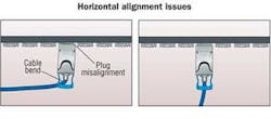
High numbers of InfiniBand cables can exert a significant force along the horizontal plane, and specifically on the connector plane of the switch. For example, if the cable emerges from the rear of the connector at too sharp an angle, excessmechanical force can be transmitted along the cable as well as into the circuit board located inside the connector. Excessive side forces exerted by the cable can also misalign the plug in the equipment-mounted receptacle (see figure, "Horizontal alignment issues"). These forces can potentially damage the connector, degrade performance or even lead to connection failure.
To help manage this weight, cabling tie bars should beinstalled to support InfiniBand cables just past the point of connection into the switch, providing strain relief along the horizontal plane. Tie bars facilitate the correct alignment of cable and plug into the port, and help installers observe manufacturer and bend radius requirements of cable close to the connector. The bars also help keep cables clear from spaces directly behind server and switch equipment, reducing thermal resistance through the equipment and promoting effective cooling and airflow.
• Vertical routing and bundling. Cluster designs require significant numbers of interconnect cables to function at top speeds, and InfiniBand cables can complicate traditional routing and management schemes. For example, thick InfiniBand cabling will fill vertical pathways more quickly than other types. Also, if cables are positioned too tightly together, they can severely impact airflow through the racks or cabinets containing the equipment that affects switch reliability and facility uptime.
These factors should be taken intoaccount during the design phase, and wide vertical pathways should be specifiedaccordingly. Cabinets and racks used for HPC clusters should have a wide design and incorporate side channels that facilitate routing and management of thickercable bundles. Wider cabinets also allow more effective cable slack management so that large cable bundles can be managed without hindering airflow.
InfiniBand assemblies are slightly more prone to internal damage when bent, which can cause signal reflection and degrade performance. Using vertical fingers aligned with each rack unit eases the transition of cables from the horizontal pathways to vertical spaces. The fingers should have smooth, rounded edges to further support bendradius requirements and reduce the potential for damage to cables.
Finally, to maintain network integrity,InfiniBand cables should be bundled with hook-and-loop or elastomeric fastener cable ties that protect against over-tensioning.
An application example
Let"s consider an example HPC cluster to see how InfiniBand design and cable management impact a real-life installation:
Switches and their connections to servers can be arranged in several ways to constitute the switching fabric. In small to medium sized clusters, several 24-port switches can connect directly to server nodes; in large clusters, there may be two tiers of switches. Other InfiniBand switches are available with as many as 288 ports.
Cabling a cluster together can be a challenge, asInfiniBand links are commonly deployed in point-to-pointarchitectures rather than the structured cabling config-urations used for Ethernet-based links. Point-to-point layouts minimize the number of connectors per channel to help meet the link loss budget. But with no patching or crossconnectlocations, several design and installation decisions must be navigated for successful deployment.
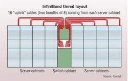
The first decision is on the configuration of the clusteritself, to determine cabling distances between active equipment. Although cluster designs vary within the industry, tiered switch configurations are popular for their modularity and scala-bility. Tiered layouts include multiple server cabinets holding up to 36 1U servers, each linked to one or two edge switches (i.e., the first tier); and one cabinet containing the switches (i.e., the second tier) that link back to edge switches via an interconnect fabric and then out to the wider network.
TIA-942 recommends that the cabinets be laid out in a row, in accordance with standard data center practice. In a tiered layout, second-tier switches would be positioned in the middle of the row for greatest ease of point-to-point cabling(see figure, "InfiniBand tiered layout").
The second decision is to match the length and gauge of each InfiniBand cable to its application in the cluster. In a tiered cluster layout, there are two distinct cable applications to measure: intra-cabinet, from servers to first-tier edge switches; andinter-cabinet, from edge switches to second tier switchlocated in a central cabinet.
Intra-cabinet server-to-switch "downlinks" are limitedin length to about 3 meters at most, depending on whereswitches are located in the rack with respect to servers, and taking into account good cabling layout practice. Shorter InfiniBand cables can be ordered with thinner conductors (e.g., 30 gauge) and have the advantages of being smaller in diameter, easier to route and manage, and occupying less cabinet space.
In contrast, the lengths of inter-cabinet "uplinks" depend on the point-to-point spans from first-tier switches to second-tier switch, including horizontal distance overhead (to allow easier access for future moves, adds, and changes) and vertical pathways within cabinets. These distances commonly are greaterthan 7 meters, so thicker conductors (e.g., 24- or 26-gauge) are required for InfiniBand cables to reach these lengths.Cable lengths should be rounded up to the nearest meter,since these natural lengths are available from most suppliers.
The third decision is to quantify the number of downlink and uplink cables in the cluster, and determine how to route them effectively. The figure, "Practical tiered routing solutions,"illustrates routing considerations for a tiered cluster with a 2:1 downlink-to-uplink ratio. At the server cabinet, 32 thinner InfiniBand downlink cables are routed along the left side, which conserves vertical pathway space on the right forother connections. At the switch cabinet, two 8-cableInfiniBand uplink bundles run from each server cabinet to the second-tier switch, for a total of 128 cables. These thickerInfiniBand bundles should be split down each side of theswitch cabinet to optimize cable routing and pathway fill.

The ratio of downlinks to uplinks is a critical design parameter in cluster configurations. From a computing perspective, the goal is to provide enough uplinks to reduce the probability that a message from any one server to another will encounter a blocked path, which would increase processing times. From a physical layer perspective, the ratio directly impacts the number of interconnect cables that need to be routed and managed. This ratio will differ between clusters, so be prepared for a wide variation in the number, size, and density of interconnect cabling.
Check your routing strategy
High transmission rates are generally less tolerant to poorcable installation practices, so you"ll need to develop andfollow a routing strategy that prevents cabling congestion inany area of the cluster. Both InfiniBand handling characteristics and point-to-point architecture differ from Ethernetcabling, so special attention must be paid to observe vendor-cited bend radius requirements.
ROBERT ELLIOT is a product development manager at Panduit (www.panduit.com).

