With PoE+ getting hot, keep your 802.3at apps cool
Your choice of twisted-pair cable could affect the heat generated from deploying Power over Ethernet Plus.
The allure of deploying power concurrent with data over telecommunications cabling is undeniable. The benefits of IEEE 802.3af-based Power over Ethernet (PoE) equipment include infrastructure management, lowered power consumption, reduced operational costs in the case of applications such as Voice over Internet Protocol (VoIP), and even improved safety due to separation from the building's main alternating-current (AC) power rung.
With its capability to deliver up to 12.95 watts (W) to the powered device (PD) at a safe nominal 48 volts direct current (DC) over Category 3/Class C and higher-rated structured cabling, IEEE 802.3af PoE (soon to be known as "Type 1") systems can easily support:
- Internet Protocol (IP)-based voice and video transmission equipment;
- IP-based network security cameras;
- Wireless access points;
- Radio frequency identification (RFID) tag readers;
- Building automation systems, including thermostats, smoke detectors, alarm systems,security access, industrial clocks/time-keepers, badge readers;
- Print servers;
- Bar code scanners.
In 2005, the IEEE (www.ieee.org) recognized an opportunity to enhance the capabilities ofpower sourcing equipment (PSE) to deliver even more power to potential support other devices, such as:
- Laptop computers;
- Thin clients, typically running Web browsers orremote desktop software applications;
- Security cameras with pan/tilt/zoom capabilities;
- IP television;
- Biometric sensors;
- WiMax transceivers providing wireless data over long distances, such as point-to-point links and mobile cellular access;
- High volumes of other devices that require additional power.
In support of this need, the IEEE 802.3at task force initiated specification of the PoE Plus or "Type 2" system that can deliver up to 29.5 W to the PD at a safe nominal 53 volts DC over legacy TIA Category 5/ISP Class D: 1995 and higher-rated structured cabling. For new installations, however, cabling should meet or exceed Category 5e/Class D: 2002 requirements. Type 2 classification requirements are expected to publish as IEEE 802.3at in mid-2009.
With power comes challenges
The development of the pending PoE Plus requirements brought to light a significant new challenge in the specification ofpower delivery over structured cabling. For the first time,due to the higher power delivered by Type 2 PSE devices,IEEE needed to understand the temperature rise within thecabling caused by applied currents, and subsequently spe-cify the PoE Plus application operating environment in sucha way as to ensure that proper cabling system transmissionperformance is maintained. To move forward, IEEE enlisted the assistance of the TIA and ISO cabling standards-development bodies to characterize the current-carrying capacity of various categories of twisted-pair cables.
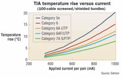
After extensive study and significant data collection, the TIA developed profiles of temperature rise versus applied current per pair for Category 5e, 6, and 6A cables configured in a 100-cable bundle. Interestingly, these profiles were created primarily based upon analysis of the performance ofunshielded twisted-pair (UTP) cables. They were later corroborated by data submitted to the ISO committee.
As expected, because Category 5e cables have the smallest conductor diameter, they also have the worst heat dissipationperformance and exhibit the greatest temperature rise due toapplied current. (Category 5 cables were excluded from thestudy because they are no longer recommended by the TIAfor new installations.) IEEE adopted the baseline profile forCategory 5e cables as representative of the worst-case current carrying capacity for cables supporting PoE Plus.
Additional TIA guidance recommended that a maximum temperature increase of 10° C, up to an absolute maximum temperature of 60° C, would be an acceptable operating environment for cabling supporting the PoE Plus applied current levels. In consideration of this input, IEEE chose to reduce the maximum temperature for Type 2 operation to 50° C, which eliminated the need for complicated power de-rating at elevated temperatures.
Next, the IEEE had to identify a maximum DC cable current that would not create a temperature rise in excess of10° C. An analysis of the worst-case Category 5e current-carrying capacity profile led IEEE PoE Plus system specifiers to target 600 mA as the maximum DC cable current for Type 2devices, which, according to the TIA profile, results in a7.2° C rise in cable temperature. Although this rise is less than the maximum 10° C value recommended, it provides valuable system headroom that helps to offset additional increases ininsertion loss due to elevated temperatures, and to minimize the risk of premature aging of the jacketing materials. Operating margin against excessive temperature rise is especially critical because this condition cannot be ascertained in the field.
An additional outcome of the TIA investigation was the understanding that higher temperature rises occur as cable bundle size increases. Analysis of the worst-case Category 5e profile resulted in the TIA providing general guidance that the maximum power injected into any cable bundle shall notexceed 5 kW up to 45° C. This constraint is likely to be furthertightened to accommodate temperatures up to the IEEEmaximum of 50° C.
Interestingly, while the IEEE acknowledges that cable cur-rent-carrying capacity is a function of cable type and installation practices (e.g., bundling), it is outside the scope of the proposed 802.3at standard to address these considerations. It is anticipated that the TIA will address these issues in afuture Telecommunications Systems Bulletin (TSB), which isexpected to describe environmental conditions of installedcabling, including bundled cabling and cabling in conduit;heat-dissipation profiles of different categories and types ofcables; and how these conditions and profiles might impactthe capability of telecommunications cabling to support the PoE Plus application.
Keeping cool
For the first time, managing heat build-up in structuredcabling must be taken into consideration in new and retrofit installations. The main challenges in designing PoE-Plus-ready cabling plants are:
With no easy method to cool down hot pathways (think of a ceiling space in Arizona) or to monitor PoE Plus-induced temperature rise in the installed cabling, the recommended approach to minimize the risks associated with excessive temperature rise is to select cabling media that has superior heat dissipation performance to start with. The TIA current-carrying capacity profiles are helpful in that they clearly demonstrate relative advantages between select media types (e.g., Category 6A UTP cables have better heat-dissipation performance than Category 5e UTP and Category 6 UTP cables).
The story these profiles tell, however, is incomplete.Specifically, they do not address the performance of Category 6A screened (F/UTP) and Category 7A fully shielded(S/FTP) cables.
Recent lab tests conducted by Siemon investigated the current-carrying capacity of riser (CMR) and plenum (CMP) Category 6A F/UTP and Category 7A S/FTP cables (see sidebar, page 20). Test cables were arranged in accordance with the TIA 100-bundle cable configuration, and the worst-case temperature rise for each media type was profiled. Reference Category 6A UTP measurements were collected and used to normalize the lab data to the TIA Category 6A data (see adjacent figures). Worst-case temperature rise for each media type with600 mA applied current was also calculated. (Note that thecurrent-carrying capacity of Category 7 cables isexpected to be equivalent to Category 7A cables because their physical construction is so similar.)
Heat-dissipation myths dispelled
Because metal has a higher conductivity than thermoplastic jacketing materials, a thermal model can be used to predict that screened and fully shielded cables have better heat dissipation than UTP cables. The data collected in the Siemon laboratories substantiates the model and demonstrates that screened cables exhibit better heat dissipation than UTP cables. The data also shows fully shielded cables have the best heat dissipation properties of all copper twisted-pair media types.
Unfortunately, there continues to be a misconception that screened and fully shielded systems will "trap" the heat generated by PoE and PoE Plus applications. But this notion can be easily dispelled by models and laboratory data.
Of note, the PoE Plus application is targeted to be compatible with 10Base-T, 100Base-T, and 1000Base-T, while compatibility with 10GBase-T is noted as not being precluded by the new standard. Thus, in an attempt to operate over the largest possible percentage of the installed cabling base, the pending 802.3at standard specifies ISO 11801 Class D: 1995 and TIA 568-B.2 Category 5-compliant cabling systems having DC loop resistances less than or equal to 25 ¿ as the minimum grade of cabling capable of supporting PoE Plus. (These are legacy grades of 100-MHz cabling; the TIA recognized 568-B.2 Category 5e cabling and ISO recognizes Class D: 2002 cabling for new installations.)
While these objectives represent good news for those with an installed base of Category 5/5e or Class D:1995/D:2002 cabling, these cabling systems typically have poor heat-dissipation properties, and much better choices exist for those specifying new or retrofit cabling plants today.
Specifying cabling with better heat-dissipation characteristics means: Operating temperatures are less likelyto exceed 50° C; certain common installationpractices, such as bundling, are less likely to impact overall temperature rise; undesirable increases ininsertion loss due to elevated temperatures will be minimized; the risk of premature aging of cabling jacket materials is reduced;
Good heat-dissipation performance exhibited by the cabling plant is critical because no methods exist for monitoring temperature rise in an installation or mitigating a high-temperature environment.
Historically, a comfortable level of performance margin is considered to be 50% headroom to standards-specified limits, which would be equivalent to 6 dB headroom for a transmission-performanceparameter. Following these guidelines, the solutions that offer the most desirable levels of heat-dissipation headroom in support of PoE Plus are Category 6A F/UTP and Category 7A S/FTP systems. In fact, Category 7A S/FTP cabling systems dissipate at least 60% more heat than Category 5e cables.
Beyond PoE Plus
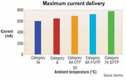
With the many functional and cost-saving advantages associated with PoE Plus, it is easy to predict that the need to supply even more power to the PD is just a few years away. The figure "Maximum current delivery" (page 18)shows the maximum current that can beapplied over different media types at 50° C without exceeding maximum temperature-rise constraints.
Based on their superior current-carrying ability, it is a safe bet that Category 6A and higher-rated cabling will be the targeted media to support tomorrow's high-performance powering applications.
VALERIE MAGUIRE is global sales engineer with Siemon (www.siemon.com). This article is derived from her white paper, "IEEE 802.3at PoE Plus Operating Efficiency: How to Keep a Hot Application Running Cool."
Temperature de-rating of UTP vs. F/UTP and S/FTP systems
It is well known that insertion loss increases (i.e., signalsattenuate more) as the ambient temperature in thecabling environment increases. To address this issue, both the TIA and ISO specify a temperature-dependent de-rating factor for use in determining the length by which the maximum horizontal cable distance should be reduced to ensure compliance with specified channel insertion losslimits at temperatures above ambient (20° C).
It is not well known, however, that the de-rating adjustment made for UTP cabling allows for a much greater increase in insertion loss than the de-rating adjustment specified forF/UTP and S/FTP systems. For UTP, a 0.4% increase per° C is allowed from 20° to 40° C and a 0.6% increase per °C from 40° to 60° C. For F/UTP and S/FTP, a 0.2% increase per ° C is allowed across the full range, from 20° to 60° C.
This indicates that F/UTP and S/FTP cabling systems have more stable transmission performance at elevated temperatures, and the two media types are better suited to support applications such as PoE Plus than UTP cabling systems are. —VM
Overview of laboratory test configuration
Laboratory tests referred to in this article were conducted at Siemon Labs, Watertown, CT. The test procedure went asfollows:
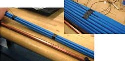
Beginning with a core consisting of a 1.2-meter cable, layers of 1.2-meter cable lengths were carefully applied around the core to create a symmetrical 6-around-1 bundle.
The bundle layer was secured with electrical tape and a temperature-sensing thermocouple was embedded into the surface of the cable jacket.
Additional 1.2-meter cable lengths were applied, taped, and embedded with thermocouples to grow the bundle size incrementally from an 18-around-1 bundle, to a 36-around-1 bundle, to a 60-, then 90-, and finally a 100-around-1 bundle.
The finished 100-around-1 bundle was suspended in air at a minimum distance of 0.3 meters from any object in all directions. The ends of the bundle were covered with insulating foam to eliminate heat dissipation from the ends of the bundle, thereby ensuring worst-case heat build-up. Test leads from a continuous current power supply were attached to all four pairs in the cable bundle.
The current on the power supply was set to 720 mA for each pair, for a total applied current of 2.88 A. Initial sample temperatures were measured and recorded for each bundle layer. Temperature readings were collected at hourly intervals from each thermocouple. Final temperature readings were collected after the bundle had stabilized for four hours. As expected, the highest temperature rise was recorded at the thermocouple closest to the core of the bundle. The cable bundle's thermal resistance was determined from the measurements, and a heat dissipation profile, including performance at 600 mA, was derived.
Measurement accuracy is approximated to be ±1° C. —VM


