Inspection a critical piece of fiber-plant testing
Tools such as fault locators and microscopes are must-haves for technicians commissioning fiber-optic systems in any environment.
After all the cables in a fiber-optic network are installed, spliced, and terminated, they must be tested. For every fiber-optic cable plant, you need to test for continuity and polarity, end-to-end insertion loss, and then troubleshoot any problems on every fiber in every cable. If it’s a long outside-plant cable with intermediate splices, you will probably want to verify the individual splices with an optical time-domain reflectometer (OTDR) test also, because that is the only way to ensure that each splice is good. If you are the network user, you may also be interested in testing transmitter and receiver power, as power is the measurement that tells you whether or not the system is operating properly.

Depending on the source of light coming from a fiber, it may or may not be safe to look directly at the fiber. Light from a VFL may be hazardous.
Testing is the subject of the majority of industry standards, as there is a need to verify component and system specifications in a consistent manner. Most of the tests in fiber-optic standards that come from the Telecommunications Industry Association (TIA; www.tiaonline.org) and the International Organization for Standardization (ISO; www.iso.org) relate to manufacturing-testing, to verify component performance; they are not relevant to installation testing.
Perhaps the most important test is insertion loss of an installed fiber-optic cable plant, performed with a light source and power meter (LSPM) or optical-loss test set (OLTS). The test is required by all international standards to ensure the cable plant is within the loss budget before acceptance of the installation.
Testing fiber-optic components and cable plants requires making several tests and measurements. Some tests involve installer inspection and judgment, such as visual inspection or tracing, while some use sophisticated instruments that provide direct measurements. Optical power, required for measuring source power, receiver power and, when used with a test source, loss or attenuation, is the most important parameter. It is required for almost every fiber-optic test. Backscatter measurements made by an OTDR are the next-most important measurements, especially for testing outside plant installations and troubleshooting. Measuring geometrical parameters of fiber and bandwidth or dispersion are essential for fiber manufacturers, but not relevant to field testing. Troubleshooting installed cables and networks is required in every installation.
This article focuses on visual inspection techniques and the tools available to conduct these inspections.
Visual tracing
Continuity checking with a visual fiber tracer can trace a path of fiber from one end to another through many connections, verifying continuity, correct connections, and duplex connector polarity. A visual fiber tracer looks like a flashlight or pen-like instrument with a light bulb or light-emitting diode (LED) source that mates to a fiber-optic connector. Attach the fiber you’re going to test to the visual tracer and look at the other end of the fiber to see the light transmitted through the core of the fiber. If there is no light at the far end, go back to intermediate connections to find the bad section of the cable.
A good example of how a visual tracer can save time and money is testing fiber on a reel before you install it to make sure it has not been damaged during shipment. First look for visible signs of damage to the fiber on the reel, like cracked or broken reels, or kinks in the cable. During testing, visual tracers help also identify the next fiber to be tested for loss with the test kit.
When connecting cables at patch panels, use the visual tracer to make sure each connection is the correct two fibers. To make certain the proper fiber is connected between the transmitter and receiver, use the visual tracer in place of the transmitter and your eye instead of the receiver to verify the connection. Follow all rules of eye safety when working with visual tracers.
Visual fault location
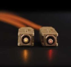
A higher-power version of the visual tracer called a visual fault locator (VFL) uses a visible laser that can also find faults. The red laser light is powerful enough for continuity checking or to trace fibers for several kilometers, identify splices in splice trays, and show breaks in fibers or high-loss connectors. You can see the loss of light at a fiber break by the bright red light from the VFL, even through the jacket of many yellow or orange simplex cables (but not with black or gray jackets, of course).
The VFL’s most important use is finding faults in short cables or near the connector where OTDRs cannot find them. You can also use the VFL to visually verify and optimize mechanical splices or prepolished splice-type fiber-optic connectors. By visually minimizing the light lost, you can get the lowest-loss splice. No other method will assure you of high yield with those connectors.
VFLs require a warning on eye safety. They use visible light. The power level is high and you should not look directly at it. You will find it quite uncomfortable to look directly at the output of a fiber illuminated by a VFL, so when tracing fibers, look to the side of the fiber to see if VFL light is present.
Connector inspection with microscope
Fiber-optic inspection microscopes are used to inspect connectors to confirm proper polishing and find faults like scratches, polishing defects, and dirt. They can be used both to check the quality of the termination procedure and to diagnose problems. A well-made connector will have a smooth, polished, scratch-free finish and the fiber will not show any signs of cracks, chips, or areas where the fiber is either protruding from the end of the ferrule or pulling back into it.
The magnification for viewing connectors can be 30 to 400 power, but it is best to use a medium magnification. If the magnification is too low, critical details may not be visible. Inspection with a very high magnification may cause the viewer to be too critical, rejecting good connectors. Multimode connectors should use magnifications in the range of 100 to 200x, and singlemode can use higher magnification, up to 400x.
A better solution is to use medium magnification, but inspect the connector three ways.
- Viewing directly at the end of the polished surface with coaxial or oblique lighting
- Viewing directly with light transmitted through the core
- Viewing at an angle with lighting from the opposite angle or with quite oblique lighting
Viewing directly allows seeing the fiber and the ferrule hole, determining if the ferrule hole is of the proper size, the fiber is centered in the hole, and a proper amount of adhesive has been applied. Only the largest scratches may be visible this way, however. Adding light transmitted through the core will allow you to see cracks in the end of the fiber, caused by pressure or heat during the polish process.
Viewing the end of the connector at an angle, while lighting it from the opposite side at approximately the same angle, or using low-angle lighting and viewing directly will allow the best inspection for the quality of polish and possible scratches. The shadowing effect of angular viewing or lighting enhances the contrast of scratches against the mirror-smooth polished surface of the glass.
One needs to be careful while inspecting connectors. The tendency is to be overly critical sometimes, especially at high magnification. Only defects over the fiber core are generally considered a problem. Chipping of the glass around the outside of the cladding is not unusual and will have no effect on the connector’s ability to couple light in the core on multimode fibers. Likewise, scratches only on the cladding should not cause any loss problems.
The best microscopes allow you to inspect the connector from several angles, either by tilting the connector or having angle illumination to get the best picture of what’s going on. Check to make sure the microscope has an easy-to-use adapter to attach the connectors of interest to the microscope.
Video-readout microscopes are now available; they allow easier viewing of the connector endface, and some even have software that analyzes the finish. While they are much more expensive than normal optical microscopes, they will make inspection easier and greatly increase productivity.
Remember to check that no power is present in the cable before you look at it in a microscope, in order to protect your eyes. The microscope will concentrate any power in the fiber and focus it into your eye, with potentially hazardous results. Some microscopes have filters to stop the infrared radiation from transmitters to minimize this problem.
Jim Hayes is co-founder of The Fiber Optic Association (FOA; www.thefoa.org). He has more than 30 years’ experience in fiber-optic communications. This article is excerpted from Hayes’s most recent book FOA Reference Guide to Fiber Optics: Study Guide to FOA Certification, published by The FOA.
New FOA book serves as certification study guide
FOA Reference Guide to Fiber Optics: Study Guide to FOA Certification, the book from which this article is excerpted, is the newest textbook from The Fiber Optic Association. Compared to its predecessor, Fiber Optic Technicians Manual, the new book has reorganized materials in a manner that, according to author Jim Hayes, makes them better arranged for reference and training. The book also includes material on fiber-optic data links, fiber-to-the-home, and testing, which were not in the previous publication.
Other new items include chapters on network design and installation, which combine materials that previously were scattered throughout the Technicians Manual. The book is derived from the FOA Online Fiber Optic Reference Guide Web site.
Since it was founded in 1995, the FOA has focused on education and certification. As of mid-2009, more than 230 FOA-approved schools have certified more than 27,000 Certified Fiber Optic Technician (CFOT) students worldwide.

