Fibre Channel over Ethernet will change architectures
The transmission method, which encapsulates Fibre Channel frames into Ethernet frames, holds the promise of a unified-fabric solution.
Data centers use multi-ple networks that present operational and maintenance issues, as each network requires dedicated electronics and cabling infrastructure. Ethernet and Fibre Channel are the typical networks, with Ethernet providing a LAN between users and computing infrastructure, while Fibre Channel provides connections between servers and storage to create a storage area network (SAN).
Fibre Channel's T11 technical committee and the Institute of Electrical and Electronics Engineers (IEEE; www.ieee.org) Data Center Bridging committee are defining standards to converge the two fabrics into a uni- fied fabric, with Fibre Channel over Ethernet (FCoE).
What is FCoE?
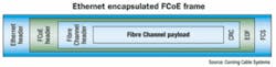
FCoE is simply a transmission method in which the Fibre Channel frame is encapsulated into an Ethernet frame at the server. The server encapsulates Fibre Channel frames into Ethernet frames before sending them over the LAN, and de-encapsulates them when FCoE frames are received. Server input/output (I/O) consolidation combines the network interface card (NIC) and host bus adapter (HBA) cards into a single converged network adapter (CNA), which reduces server cabling and power/cooling needs.
At present, the Ethernet frame is removed at the Ethernet edge switch to access the Fibre Channel frame, which is then transported to the SAN. Fibre Channel encapsulation requires use of 10-Gigabit Ethernet transmission electronics, as well as provides for increased server-to-SAN connectivity. FCoE encapsulation standards acti- vity takes place at the Fibre Channel T11.3 committee.
Fibre Channel is a deterministic protocol that guarantees delivery of information. Native Ethernet has not been deterministic and has relied on transmission control protocol (TCP) to re-transmit dropped frames. With FCoE, the Ethernet transport has been required to be updated to ensure that frames/packets are lossless without using TCP/IP protocol. The new enhanced Ethernet standard is called Converged Enhanced Ethernet (CEE). CEE standards activity takes place at the IEEE 802.1 Data Center Bridging working groups.
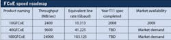
The table (page 19) provides the Fibre Channel Industry Association (FCIA; www.fibrechannel.org) FCoE speed roadmap. Where 10-Gigabit FCoE uses serial duplex fiber transmission, 40/100-Gbit FCoE speeds will require parallel optics. Data centers should install 12-fiber MPO backbone cables with OM3 fiber that can be used for 10-Gbit FCoE and provide for an effective migration path to emerging parallel optics that require an MPO interface into the switch electronics and the server.
FCoE cabling architectures
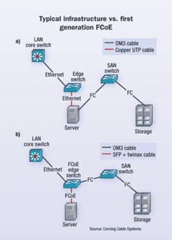
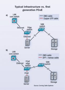
Typical data center cabling infrastructure now includes an Ethernet optical-fiber uplink to the access switches located at the server rack. Copper unshielded twisted-pair (UTP) cables then interconnect to the server NIC. Fibre Channel frames are transmitted from the server HBA to the SAN using optical fiber. Laser-optimized 50-µm multimode fiber (OM3) is the default type of optical fiber used for Ethernet and Fibre Channel transport. Category 6 or Category 5 are typical copper UTP cables for edge-switch-to-server interconnect.
First-generation FCoE implementation will focus on the edge switch and server. Ethernet OM3 optical uplinks will be received into the FCoE-enabled edge switch and then interconnected to the server CNA. Instead of copper UTP interconnects, small-form-factor pluggable + (SFP+) direct attached twinaxial copper cable is now used as the medium with significantly lower power and latency performance. The twinax copper cable will be used for distances up to 7 to 10 meters. Beyond that distance, low-cost, ultra-short reach (USR) SFP+ modules and OM3 optical fiber will be used. The encapsulated Fibre Channel frame is returned to the edge switch where the Ethernet frame is removed to access the Fibre Channel frame. The Fibre Channel frame is then transmitted to the SAN. This architecture solution reduces the server interconnect cabling and adapter card number by at least 50%.
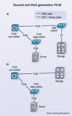
Second-generation FCoE deployments are expected to use FCoE-enabled core switches and edge switches. This architecture will continue to use basic Ethernet optical uplinks from the core switch to the edge switch and SFP+ twinax interconnects into the server. The difference occurs when the FCoE frame is transmitted back through the edge switch to the core switch over the same optical fiber previously used as the uplink to the server. At the core switch, the FCoE frame is forwarded to the SAN director, where the Ethernet frame is removed and the Fibre Channel frame is then transmitted to the storage devices. This architecture solution reduces the server interconnect cabling and adapter card number by at least 50% and eliminates the Fibre Channel HBA-to-SAN optical- fiber trunk cable.
Third-generation FCoE architecture mirrors the second generation, with the exception that the core switch now forwards the FCoE frame directly to storage, where the Fibre Channel frame is accessed. This architecture solution reduces the server interconnect cabling and adapter card number by at least 50%, eliminates the Fibre Channel HBA-to-SAN optical-fiber trunk cable, and eliminates the core switch-to-SAN director fiber trunk cable.
The FCIA had adopted specific guidance relative to the cabling physical layer. Optical connectivity shall be in accordance with IEEE 802.3ae (10GBase-SR) using OM3 optical fiber. Additionally, the guidance recommends new installs to be =100 meters to be compatible with emerging 40/100-Gbit Ethernet installs and 16/32-Gbit Fibre Channel. SFP+ is the preferred connector for copper and optical cable. This eliminates the use of 10GBase-T copper UTP/shielded twisted-pair cable.
FCoE offers a data center unified-fabric solution that simplifies operational and maintenance of the cabling infrastructure. FCoE facilitates use of low-cost Ethernet electronics and OM3 optical connectivity to support 10-, 40, and 100-Gbit data rates.
DOUG COLEMAN is manager/technology and standards with Corning Cable Systems (www.corning.com/cablesystems).

