Bonding from the busbar to the rack, and back again
While a TIA standard revision shapes up, new cable technologies claim high performance without a grounding/bonding requirement.
The Telecommunications Industry Association's (TIA; www.tiaonline.org) TR-42.16 Subcommittee continues diligent work on what will ultimately become the TIA-607-B standard, specifying the grounding (earthing) and bonding of telecommunications systems. Meeting at an almost-monthly frequency, the TR-42.16 group has made steady progress on the specs.
“The 607-B document has completed draft 6,” says Tom Turner, business development manager for grounding and bonding with Panduit (www.panduit.com). The standard-in-development is a revision of ANSI-J-STD-607-A, which also covered the grounding (earthing) and bonding of telecommunications systems in commercial buildings. Turner explains, “The J-STD-607-A standard stopped at the busbar that resided in the telecommunications space. The 607-B standard will include details of how to bond equipment in the rack space, back to that busbar.”
He adds that the installation information in the standard is likely to resemble that within the TIA-942 data-center cabling standard. At a high level, 607-B will essentially take the information in 942 and apply it to all telecommunications spaces while providing clarification as to how this can be done.
TIA aims for early 2010
Donna Ballast, standards representative for BICSI (www.bicsi.org) who sits on the TR-42.16 Subcommittee, explains, “The subcommittee met on May 5 and agreed to make modification to the current draft, and then send it out to committee ballot, which takes 30 days. The committee ballot will be reviewed in August when it will likely be approved to go out to industry ballot. We could see approval for publication in February or June 2010.”
Currently, several task groups within the committee are continuing investigation into some of the specifics that will end up in the published standard and/or an annex. Ballast states, “A ground-bar investigation is being held in a task group led by Ray Keden of ERICO. The purpose is to investigate if the section on ground bars can be written to a performance specification rather than a materials specification.”
She continues, “An annex is being proposed on electromagnetic compatibility. The task group is headed by Paul Kish of Belden. The annex is to provide an understanding of EMC and the ability of equipment or system to function satisfactorily in its electromagnetic environment. Emissions and equipment-susceptibility are two issues that EMC can impact. Data centers and central offices often contain ground grids to mitigate these effects. Also, test requirements are now being introduced into the 607-B standard. Previously, there were no requirements. Presently, there is a 2-point ground/continuity test in the current draft, and is being investigated as to whether or not there should be a ground-voltage test and a ground-current test.”
Finally, Ballast adds, “Terms and descriptions of various types of bonding and grounding schemes are being reviewed to ensure most, if not all, types are included in this standard. A task group is investigating these terms and descriptions including those used by international standards organizations.”
As usual, the TIA subcommittee doing the legwork to construct a standard has a full plate of activities, investigations, and comment resolution ahead of it.
Installation issues
The topic of grounding and bonding a telecommunications system always seems to draw intense interest, regardless of whether it is presented in a live forum (such as a conference), in a Web-based seminar-style presentation, or in an online chat. The process, it is fair to say, is challenging for system installers, and is one they do not perform very frequently as most installations still use unshielded twisted-pair (UTP) cables and traditionally jacketed fiber-optic cables. Although other parts of a structured cabling system containing metallic elements—including cable trays and equipment racks—must be bonded to ground, the UTP and fiber-optic cabling circuits themselves do not carry that requirement.
Installers who work with foiled (F/UTP) or fully shielded (S/FTP) twisted-pair cabling, however, must bond the cabling circuits to ground. So must anyone installing fiber- optic cable with a protective metallic armor. F/UTP was off the North American cabling industry's proverbial radar screen for years, even decades, until relatively recently. Once the development of the Institute of Electrical and Electronics Engineers (IEEE; www.ieee.org) 10GBase-T specifications began in earnest, focus within the cabling industry zoomed in on Category 6A performance levels, which are required to support 10GBase-T over 100 meters.
Alien noise sources—specifically, cable-to-cable noise— became the paramount issue of Category 6A performance and 10GBase-T transmissions. Because the primary performance concern was cable-to-cable crosstalk, shielded copper cables became a viable and attractive option for many to support 10GBase-T specifications. But F/UTP had more appeal than just performance.
“Initially, end users had concerns with the alien-crosstalk performance and cable diameter of UTP Category 6A cables,” says Phil Chandler, cable product line manager with Panduit. “Some end users migrated to shielded cabling systems to obtain exceptional alien-crosstalk suppression, with the added benefit of a slightly smaller cable.”
In simple terms, first-generation Category 6A UTP cables had large diameters to allow for more separation between the conductors of separate cables. The more physical space between the conductors of adjacent cables, the better alien-noise performance the cabling system would achieve. As a result, these first-generation Category 6A UTP cable designs included oval shapes, thick- jacketed round shapes, or wraparound-style elements placed between the group of four twisted pairs and the cable jacket. First-generation Category 6A UTP cable looked and felt different from the UTP constructions that installers and cabling- system end users had been familiar with when deploying typical Category 5e and 6 systems.
Shielded and unshielded
Bob Kenny, vice president and general manager of data-communications cables for General Cable Corp. (www.generalcable. com), adds that several forces pushed customers to take a close look at shielded options: “Customers suddenly felt intui- tively like they needed it. They had questions: ‘Why is the UTP cable so large?' ‘Why can't we lay the cables next to each other?' Customers had reservations over noise issues, and shielded cable was a solution.”
Kenny adds that despite all the discussion and publicity shielded cable received throughout the industry, including in this and other trade publications, “when you peel away the onion, it is still an extremely small segment of the market in North America.”
Historically, cabling-system installers and users favored UTP over shielded for reasons that included lower cost and ease of use, the latter of which results from UTP's traditionally smaller size than F/UTP and its comparatively simple termination process. The termination process of a shielded cable is key to achieving the bond to ground.
In recent months, manufacturers of the earliest, pre-standard Category 6A cable have introduced their second-generation UTP products, which are smaller in size than the originals and have essentially neutralized the size advantage/disadvantage of one medium compared to the other.
New UTP technology
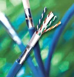
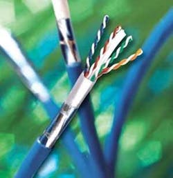
Earlier this year, Panduit and General Cable introduced a jointly developed UTP technology that they say reduces Category 6A cable size without sacrificing internal and external (alien) performance. Both Panduit TX6A 10Gig and General Cable GenSpeed10 MTP systems use discontinuous metallic elements to deliver the alien-crosstlk suppression benefits of a shielded system without the need to bond the cables to ground. The metallic elements, alternately termed “Matrix” or “Mosaic Crossblock” technology, are separated by an insulating layer. Because there is no metal-to-metal contact, there is no path for current to flow longitudinally, and thus no need for grounding. General Cable says this design innovation also allows for a smaller-diameter Category 6A cable.
“The biggest difference is that the mosaic crossblock element is non-continuous,” Kenny says, comparing the GenSpeed10 MTP with F/UTP products. “When you think of a foiled cable, it typically has a continuous metal shield. It also contains a drain wire, which is used during termination to ensure the cable is grounded properly. GenSpeed10 does not have a drain wire or a continuous metal plane.”
The upshot from an electrical performance standpoint, Kenny says, is “the ability to attenuate unwanted noise. Noise is a signal; it is a current and has the potential for energy to flow. The technology incorporates very thin, very small shield elements that impede and attenuate the flow of noise. A grounded shield is not necessarily designed to impede the flow of noise and therefore requires the use of a ground wire.”
General Cable and Panduit partner to provide an end-to-end cabling system, and introduced their new UTP Category 6A cable concepts into the market earlier this year. Panduit's Chandler succinctly describes the nuances of the cable-to-jack termination process. “It is exactly the same as UTP. The discontinuous metallic element tape is trimmed away just like a crossweb pair separator. As with any UTP solution, there is no requirement to bond or ground the cabling system.”
Those comments are echoed by Gary Bernstein, director of product management for copper systems with Leviton Network Solutions (www.leviton.com/networksolutions). Leviton collaborated with Superior Essex (www.superioressex.com) in the research, development, and production of the NextLAN 10GC AXi UTP cabling system. The “AXi” term indicates “alien-crosstalk isolation,” which Superior Essex's 10Gain XP Category 6A cable achieves through the use of a non-conductive isolation wrap with discontinuous sections of metallic material supported by a continuous polymeric film.
Leviton's Bernstein describes terminating the Superior Essex cable to Leviton connecting hardware as “easy and quick. Even though there's an isolation wrap and it looks like a foil, the installer can strip off the jacketing and the wrap. With a foiled cable, the installer has to be careful not to cut through the foil because it needs to make contact with the jack” in order to maintain the bond. That's not the case with the 10GC AXi system.
The isolation wrap's non-conductive properties make the entire termination process easier, as Bernstein further explains: “With shielded cables, either fully shielded or foiled, termination can take more time, especially from a cable-preparation standpoint. In addition to avoiding cutting the foil, the installer takes more time simply getting the cable ready for termination, and must be careful not to cut the drain wire.” He adds that the testing process is also slightly different with foiled cables: “If you install a foiled system and test it correctly, the wiremap test will check for the continuity of the shield.”
Armored fiber cable
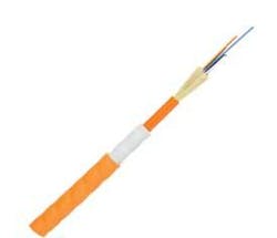
While these dual product-development efforts were taking place in the realm of twisted-pair copper cabling, similar strides were being made with multimode fiber-optic cabling. In April, Corning Cable Systems (www. corningcablesystems.com) introduced the MIC DX Armored Cable, an all-dielectric armored fiber-optic cable. Corning describes benefits of the MIC DX that sound familiar to those of the new UTP technologies, namely, ease-of-use and eliminating the need to ground/bond.
Marcus Sullivan, LAN market manager with Corning Cable Systems, describes the market conditions that prompted the cable's development: “We have seen a huge increase in the use of interlocking armor, and our channels tell us it is becoming a cable of choice. Users see the benefit of not having to install innerduct and then pull cable.”
Sullivan adds, “DX cable, as it is frequently called, provides a robust pathway because of its armor. But one of the problems with interlocking armor is that it needs to be grounded, and often it is not. Another problem is that when the interlocking armored cable is stripped, the installer leaves jagged metal edges at the end of the cable, which is a safety issue.”
Corning decided to pursue the creation of an all-dielectric armor, made of PVC. “It is difficult to manufacture extruding PVC around the cable in order to protect it,” Sullivan states. “But we asked if it was possible to fix the problems associated with interlocking armor and still provide a cable that is robust and has good performance. It requires a lot of process engineering, and a lot of chemical research went into this product's development. It's difficult to burn that much PVC and still pass the plenum test. Corning worked with its materials suppliers to accomplish that.”
The MIC DX is available in plenum, riser, and general-purpose ratings. It is 17% lighter than interlocking-armor cable and has a 12%-smaller outside diameter. Sullivan says that testing has shown the new cable to have greater tensile strength than interlocking armored cable.
In a coincidental reversal of the situation with the recently developed UTP cables, Corning claims the MIC DX's protective element is continuous, whereas interlocking armor is non-continuous. Sullivan explains, “Our all-dielectric armor is a continuous piece and does not unravel. With interlocking cable, the armor may start to unravel when it is being pulled,” thereby compromising the protection it provides.
He reports that early feedback includes positive response to the cable's smaller outside diameter. “As we're seeing in existing brownfield applications, the number-one problem is con- gested pathways,” says Sullivan. “Users who don't have the space to install innerduct have been using interlocking armor.”
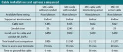
He adds that for the time being at least, and probably for the foreseeable future, Corning will offer the MIC DX as well as traditional armored cable. “Right now, the market is going to demand interlocking armor because it's what they're used to,” says Sullivan. “I believe once people see the benefit, we'll get a large conversion rate. But right now, we plan to continue both product lines.” Corning has developed a value-proposition document that compares the MIC DX to other cable types with side-by-side comparisons of characteristics including total installation cost, installation time, and grounding time.
Specific focus
General Cable's Kenny reflects that comfort and familiarity also work in the favor of his newly introduced UTP cable: “In the early 1990s, LANs were brand new and IBM Type 1 was the cable installed to support it. Today, when you find people who remember the days of Type 1, many say they do not want to return to it. LANs are not brand new; everything is existing, and many users have to live with what they have. Many of them did not set themselves up for the rigors of what it takes for the cabling to be grounded properly.”
Kenny adds, “Users want products and technologies that present the least amount of disruption possible.” The GenSpeed10 MTP's ability to fend off alien crosstalk with a construction that does not require the termination or grounding/bonding processes of foiled cable fits that bill, he says.
Kenny further explains that General's new cable is a targeted solution to the specific problem of alien crosstalk: “By using a cable with a complete shield, you're not only addressing that specific problem, but also expending tremendous overkill solving things you don't need to solve. A complete shield is designed to isolate everything, when the problem people encounter is very specific. For your specific problem, here's a specific solution. There's a particular type of noise we're interested in. The power-spectral density is well understood, and we know where the energy exists. We can prevent the unwanted noises from infecting our signal.”
He concludes, “A normal shield protects from everything over a million combinations. We believe we have a concept that targets the type of frequency that could interfere with a signal. Our approach has allowed us to place some unique elements into the design.”
Consistency on the horizon
Donna Ballast puts a punctuation mark on the conversation by reflecting on her observations: “My experience is in large government-owned campuses and data centers, where the racks are being bonded to ground. As to how they are bonded to ground, that is another story.”
She says an installation standard jointly developed by BICSI and NECA—NECA/BICSI-607—“will now provide some guidance and we should see more consistency going forward.”
PATRICK McLAUGHLIN is chief editor of Cabling Installation & Maintenance.


