When to consider an any-to-all design
While traditional point-to-point cabling still has its place in the data center, a standards-based structured cabling solution can save on equipment cost, maintenance, and power.
Many data centers today are victims of historical point-to-point cabling practices. Direct connections (i.e., from switches to servers, servers to storage, servers to other servers, etc.) can be problematic and costly, for a variety of reasons. While top of rack (ToR), End of Row (EoR) equipment mounting options are available, these should supplement but not replace a structured cabling system.
ToR and EoR equipment placement rely heavily on point-to-point cables; typically, fiber jumpers or twinax copper assemblies or stranded patch cords to connect the network or storage equipment ports to servers. In the best of data center ecosystems, a standards-based structured cabling system will provide functionality and scalability with the maximum options for current andfuture equipment.
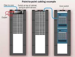
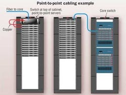
The figure at right depicts a typical point-to-pointdesign. While point-to-point proponents tout a decrease in cabling as a cost offset, further examination maynegate such savings. If a central KVM switch is used,the centralized structured cabling system would need toco-exist anyway, albeit with less channels. Newer electronics may have different channel minimum/maximum lengths, resulting in the need for new channels.
As electronics progress, the structured system may need to be added back to the data center to support future equipment choices, completely negating the savings. It will cost more to add the structured system later because pathways, spaces, and channels were not planned for and must be installed in a live environment, increasing labor costs and the likelihood of downtime. And when adding pathways and spaces, fire suppression systems and lighting may need to be moved to accommodate added overhead pathway systems. Floor voids may need to be increased and cabinets may need to be moved to allow new pathways to be routed for proper airflow.
Among other disadvantages, switch ports are dedicated to servers within a particular cabinet, which can lead to an oversubscription of ports. Suppose a rack/cabinet had the need for only 26 server connections for the entire rack. If a 48-port switch (ToR switching) or 48-port blade (point-to-point server to switch) is dedicated to the cabinet, this means that 22 additional ports are purchased while maintenance is paid on the unused ports.
A greater problem occurs when the full 48 ports are used. Adding even one new server will require the purchase of another 48-port switch. In this case, assuming two network connections for the new server, an oversubscription of 46 ports will be added to the cabinet. Even in an idle state, these excess ports consume power. Two power supplies are added to the cabinet, and active maintenance and warranty costs are also associated with theadditional switch and ports.
Many of these ToR technologies also have limitations for cabling length. Maximum lengths range from 2 to 15 meters and are more expensive than a structured cabling channel. Short channel lengths may limit locations of equipment within the shorter cable range. With a structured cabling system, however, 10GBase-T can be supported on up to 100meters of Category 6A, 7 and 7A cabling, and allows moreoptions for equipment placement within the data center.
The any-to-all system
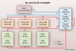
In an any-to-all design, copper and fiber patch panels areinstalled in each cabinet corresponding to copper patch panels installed in a central patching area. All fiber is run to one section of cabinets/racks in that same central patching area, which allows any equipment to be installed and connected to anyother piece of equipment via either a copper patch cord or a fiber jumper. The fixed portion of the channel remains unchanged. Pathways and spaces are planned up front to properly accommodate the cabling.
While this method requires more cabling up front, it has significant advantages concerning the life of the data center. Channels are passive and carry no reoccurring maintenance costs, unlike active electronics. If planned properly, structuredcabling systems will last at least 10 years, supporting 2 or 3 generations of active electronics. Also, the additional equipment needed for a point-to-point system will require replacement/upgrade multiple times before the structured cabling system needs to be replaced. Equipment replacement costs alone, not including ongoing maintenance fees, will negate any up front savings from using less cabling in a point-to-point system.
In the above example of an any-to-all solution, the connections all arrive in the central patching area in one location, which allows any piece of equipment requiring a fiber connection to be connected to any other fiber equipment port. Forinstance, if a cabinet has a switch that requires a fiber connection for a SAN on day one, but needs to be changed to a fiber switch connection at a later date, all that is required to connect the two ports is a fiber jumper change in the central patching area. The same is true for copper, although somedata centers zone copper connections into smaller zones by function, or based on copper length and pathway requirements. As with fiber, any copper port can be connected to any other copper port in the central patching area or within the zone.

Cabling standards are written to support 2 to 3 generations of active electronics. An any-to-all configuration assures that the fixed portion of the channels is run once and remainshighly unchanged if higher performing fiber and coppercabling plants are used. As a result, there will be less contractor visits to the site for MAC work, since the channels already exist. In addition, faster deployment times for equipment will be realized as no new cabling channels have to be run—they are simply connected via a patch cord. Predefined pathways and spaces will not impact cooling airflow or become overfilled since they can be properly sized for the cabling installed. Bearing in mind that data center structured cabling standards recommend installation of cabling to accommodate growth, all anticipated future connectivity growth needs areaccounted for with the any-to-all configuration.
With central patching, switch ports are not dedicated to cabinets that may not require them; therefore,active ports can be fully utilized as any port can be connected to any other port in the central patching area. Administration and documentation are enhanced as the patch panels are labeled (according to the standards) with thelocation at the opposite end of the channel. Also, patch cords and jumpers are easy to manage in cabinets; in contrast,labeling with a point-to-point system is limited to a labelattached to the end of a cable assembly.
With a structured high performing copper and fiber cabling infrastructure, recycling of cabling is minimized as several generations of electronics can utilize the same channels. In addition, being able to utilize all switch ports lowers the number ofswitches and power supplies, helping to contribute to green factors for a data center.
To further explain the power supply and switch port impact, again contrasting the earlier point-to-point/ToR scenario with an any-to-all scenario, the 48 ports that would normally be dedicated to a single cabinet (ToR) can now be divided up, on demand, to any of several cabinets via the central patchingarea. Where autonomous LAN segments are required, VLANs or address segmentation can be used to block visibility toother segments.
For example, the table on page 22 shows the port comparison for a data center with 20 server cabinets each housing 14 servers and requiring two network connections each (560 total ports required).
Additional power requirements
The real limitation to equipment ser-vices within a cabinet is power. As switch ports reach full utilization, the powersupplied to the cabinet may not be able to handle the load of a new server and additional switch. This may mean that new power is needed at the cabinet. You should get a complete picture of thepower required for a point-to-point solution before adoption. It may not be possible from a facilities standpoint to provide enough additional power for two devices(four power supplies in a redundantconfiguration).
Virtualization is being implementedin many data centers to decrease the number of server power supplies and to increase the operating efficiencyratios within equipment. Virtualization also reduces the number of servers and the “floor space” needed to support them, which also reduces the power load to cool the room.
Increasing the number of power supplies for a ToR configuration can negate virtualization savings. Further, as virtualized servers are retired, the number of switch ports decreases; in a ToR configuration, this can increase the number of oversubscribed ports. In an any-to-allscenario, there may be dark fiber or non-energized copper cables, but these are passive, require no power, have no reoccurring maintenance/warranty costs,and can be reused for other equipment in the future.
The efficiency of the power supply is only one power factor. To properly examine overall switch to server connections, percentage of processing load, efficiency of the power supply under various loads, required cooling, and voltage required for the overall communications must be factored into overalldata center power and efficiency numbers. From a networking standpoint, looking at port consumption or power draw varies greatly between various architectures (i.e., SFP+, 10GBASE-Tand fiber). Many of these reportedpower statistics from the manufacturers do not show the entire switch consumption, but rather make a particular architecture sound attractive by only reporting power based on consumption of anindividual port, exclusive of the rest of the switch and the higher power server network interface card at the other end of the channel.
The switch port power consumption is, in most cases, far less than the server NIC at the opposite end of the channel. There has been a shift by some vendors for short point-to-point connections within the racks or near racks, due in large part to a need for 10-GbE copper connections and a lack of mass-manufactured low power 10GBase-T counterparts using a structured system. The original 10GBase-T chips had a powerrequirement of 10 to 17 watts per portirrespective of the switch and server power requirements. But this is changing as each new version of silicon manufactured for 10GBase-T is significantly lower power than the previous iteration.
If a point-to-point solution is used for copper 10-GbE communications,coexistance with a structured any-to-all system allows new technologies, such as lower power 10GBase-T, to be implemented simply by installing it and connecting it via a patch cord.
Cooling considerations
Cooling requirements are oftenexpressed as a function of power, but improper placement of equipment can wreak havoc on the best cooling plans. Point-to-point systems can land-lock equipment placement.
The ability to place equipment where it makes most sense for power and cooling can save having to purchase additional PDU whips, and in some cases, supplemental or in-row cooling for hot spots. In point-to-point configurations, placement choicesmay be restricted to cabinets where open switch ports exist so as to avoidadditional switch purchases. But this can lead to hot spots, which can have detrimental affects to neighboring equipment within that same cooling zone.
Hot spots can be reduced with an any-to-all structured cabling system byallowing equipment to be placed where it makes the most sense for power and cooling instead of being land-locked by ToR restrictions. According to the Uptime Institute (www.uptimeinstitute.com), the failure rate for equipment in the top third of the rack is 3x greater than that of equipment at the lower two-thirds. In a structured cabling system, the passive components (cabling) are placed in the upper position, leaving the cooler spaces below for the equipment.
If a data center does not have enough cooling for equipment, placing the switches in a ToR position may cause them to fail prematurely due to heat, since cold air supplied from under a raised floor will warm as it rises.
Counting the cost
While there are several instances where point-to-point Top of Rack or End of Row connections make sense, an overall study that includes total equipment cost, port utilization, maintenance, and power cost over time should be undertaken—involving both facilities and networking—to make the best overall decision.
CARRIE HIGBIE is global director of data center solutions and services at Siemon (www.siemon.com). This article is derived from a more-comprehensive white paper, which can be found on Siemon's Web site.
Assess your own situation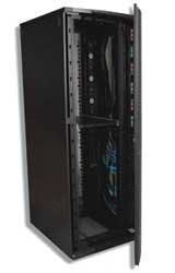
Siemon has developed several products to assist data center designers develop highly scalable, flexible and easy to maintain systems to support various generations of equipment—singularly or in conjunction with Top of Rack systems. The VersaPOD system, for example (pictured), utilizes a central Zero-U patching zone between bayed cabinets. This spaceallows for any combination of copper andfiber patching. Should the customer mount the switch in the top of one cabinet, the corner posts are recessed, allowing cabinet-to-cabinet connections that permit a switch to support multiple server cabinets for an End of Row patching configuration, increasing utilization of the switch ports. The company claims the configuration can lower the number of switches required and save energy while providing versatile, high-density patching options for both copper and fiber.

