Maximizing 802.11n with the right structured cabling
Specifications that include the TIA-569 standard and TSB-162 can help you plan for pathway and wireless performance implications.
New IEEE 802.11n wireless networking products offer faster data rates and improved coverage, addressing the drawbacks of legacy wireless networking products. 802.11n is a proposed amendment to the IEEE 802.11 wireless networking standard defining a communication protocol and waveform to achieve unprecedented wireless data rates. Although the amendment has yet to be ratified(expected within a year), most wireless vendors are selling products now that are compliant with the 802.11n draft specification.
“Wi-Fi Certified,” a trademark of the Wi-Fi Alliance (www.wi-fi.org) based on the IEEE 802.11 standards, is intended to verify interoperability between wirelessdevices from different manufacturers. The Wi-FiAlliance began testing and certifying 802.11n draft 2.0 products for interoperability in June 2007. Althoughthe 802.11n amendment is still a draft version, theWi-Fi Certified products available from most vendors means there is little risk in migrating to 802.11nwireless networking products.
There is risk, however, that your existing cablinginfrastructure is inadequate to handle the higher data rates anticipated with 802.11n products.
The reason is new wireless products use advanced RFsignal processing (multiple input/multiple output[MIMO] antennas and beam-forming), channel-bonded 40-MHz channels, and frame aggregation to achieve unprecedented wireless data rates. Many wireless access points from leading vendors are capable of operating in 802.11a/b/g/n modes. In addition, many of these products are dual radio, operating in the 2.4- and 5-GHz bands simultaneously, thereby doubling the traffic through the access point relative to single radio implementations. Although performance varies from vendor to vendor, the data throughput of many of these products may challenge the network operator's existing cable infrastructure.
While you can deploy 802.11n access points in an existing wireless network, the theoretical 802.11n peak performance will be degraded somewhat byexisting 802.11a/b/g client devices (although connectivity may improve). As existing client devices are replaced with 802.11n-capable devices, however, the overall network capability will improve.
Signaling rate vs. data throughput
To best understand the implications of 802.11n on the cabling infrastructure, you need to determine thedata throughput for the existing equipment and thencompare it with the data throughput capability of 802.11n technology. Product vendors' claims fordata rate are actually a signaling rate within eachradio packet. From the cabling standpoint, however, themetric of interest is data through-put rate, which your cabling infrastructure must be capable of transporting. The actualdata throughput rate may be quite a bit lower than the advertised data rate, which is really an over-the-air signaling rate. The signaling rate is standardized by IEEE 802.11n, but there are no standards for testing data throughput rate.
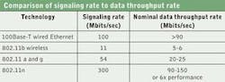
The table on page 30 makes a familiar comparison of signaling and data throughput rates. A 100Base-T network will have a 100-Mbit/sec signaling rate (within the data packets). The 100Base-T measured Ethernet throughput of a file transfer is greater than 90 Mbits/sec, and perhaps very close to100 Mbits/sec. But in the wireless network, the data throughput rate is quite a bit different from the signaling rate.
With 802.11b networks, the vendor-specified data rate—actually, the signaling rate—is 11 Mbits/sec, but the measured data throughput is more like 5 to 6 Mbits/sec. (This is in ascenario with no contention; i.e., one client device and one access point.) Likewise, with 802.11a/g/n products, the actualdata throughput, measured at the Ethernet port, will be less than half of the specified signaling rate. As the table shows, however, the 802.11n technology will offer approximately 6x the actual data throughput offered by 802.11a/g; thus, the need to consider the impact on the cabling infrastructure.
802.11n products share their transmission medium—the airwaves—and they operate half-duplex, somewhat analogous to Ethernet hubs. Contention, interference, and radiofrequency noise will degrade both signaling rate anddata throughput. Even so, 802.11n offers a ratherremarkable improvement in data throughput rate.
The impact of 6x performance relative to an existing 802.11a/g infrastructure clearly needs to be examined. This means up to 150 Mbits/sec data throughput data rate perradio, and 200 Mbits/sec for the 2-radio access point, which requires cabling for 1000Base-T (Gigabit Ethernet) versus100Base-TX (Fast Ethernet).
TIA-568-C no longer recognizes Category 5 cabling, butrecertifying or testing the installed infrastructure for Gigabit Ethernet is an option. For optimal performance, verify that the wireless access point, switch, and/or control portsinvolved are 1000Base-T capable. Oddly enough, many low-end 802.11n access points do not have a Gigabit Ethernet port.
TIA guidelines for wireless
The Telecommunications Industry Association's (TIA; www.tiaonline.org) TSB-162 Telecommunications Cabling Guidelines for Wireless Access Points provides guidelines on the topology,design, installation, and testing of cabling infrastructure for supporting wireless LANs (WLAN) in compliance with the ANSI/TIA/EIA-568-B.1 and 569-B standards for supporting WLAN in customer premises. TSB-162 is not a standard, but rather contains technical material that may be useful to industry and users. It was created by the TIA TR-42 engineering committee and released in March 2006. TIA-568-B.1 and B.2 are now incorporated into the newly released ANSI/TIA-568-C family of standards, but the guidelines of TSB-162 remain unaffected.
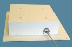
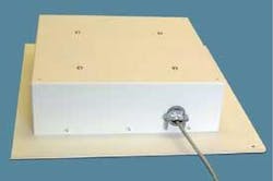
TSB-162 states that cabling should be installed and performance tested per existing 568-B.2 standards. Determination of exact cell size and placement of the access point is outside the scope of the bulletin, but the guideline does recommend use of an RF planner (either a physical site survey or simulation) to establish coverage for locations that include wall-mount above the drop ceiling, wall-mount below the drop ceiling, andin-grid ceiling mount. Telecommunications enclosures (TE) can be mounted in a ceiling panel to provide access pointsecurity or aesthetics.
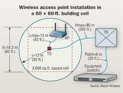
The bulletin recommends a square cell with a telecommunication outlet (TO) placed at the center of the square, with a patch cord running to the access point. TSB-162 also includes an example of a 60 x 60-foot square building cell, as shown in the figure above. This 3,600-square-foot cell represents a typical commercial building bay size, and agrees reasonably well with wireless vendor recommendations for 3,000-square-foot cell sizes to support wireless Voice over IP (VoIP). Pending completion of a wireless site survey and design, the access point can be located anywhere within the cell. The TO is connected to the telecommunications room and, subsequently, to the equipment. This approach satisfies both the TIA-568-B cable length restrictions and the WLAN design criterion foraccess point location.
TSB-162 also describes both local and remote poweringvia IEEE 802.3af-compliant power over balanced twisted pair (Power over Ethernet). Most vendors' wireless access points can be powered by Power over Ethernet, but some require 802.3at Power over Ethernet Plus. Typically, 802.11n products require close to the 12.95 watts delivered by 802.3af sources if bothradios are used. Alternating current power supplies should not be installed above the ceiling, except in an approved ceiling access enclosure.
In accordance with the TIA-569 standard, a TE may be used to enclose wireless access points. Suspended ceiling space for horizontal connection points are acceptable so long as the space is accessible without moving building fixtures, equipment, or heavy furniture. Access to the TE should be secure, andcables that enter the TE are to be protected from sheath abrasion and conductor deformation by using grommets, bushings, and cable management hardware. A TE should serve an area not greater than 3,600 square feet, and a minimum of 3 inches of clear vertical space is to be available about the ceiling tiles for horizontal cabling and pathways.
Although 802.11n is capable of providing coverage over larger areas, many vendors recommend using the same density of access points used in 802.11a/b/g networks. This is consistent with TIA standards and vendor recommendations, and anticipates applications (such as VoIP and video)requiring a higher signal-to-noise ratiothan simple data applications.
Cabling for antennas
802.11n access points may require 3 to 6antennas. 802.11a/b/g products use switched antenna diversity, where only one transmits and one receives at a time. The access point selects which antenna to use based on signal quality. New 802.11n products use MIMO transceivers where multiple antennas can be transmitting and, upon receiving the waveform, the signal is constructively combined. Therefore, to achieve the best MIMO performance, all of the access point RF connectors should be attached to unobstructed antennas.
Some access points have non-detachable or integrated antennas. Ideally, antennas should be unobstructed by ceiling tiles or other objects, and 2.4 and 5 GHz antennas should be spaced about 4 and 2 inches apart, respectively. (Beyond a minimum spacing, there is no advantage in so-called “spacing in increments of wavelength.”) Use appropriately rated coaxial antenna cable, such as UL Type CL2Pm, for ceiling installations.
For best radio frequency coverage, the ideal location for the access point's antenna is in the ceiling. The National Electrical Code (NEC) provides guidance on installation in or above a suspended ceiling. It differentiates a “ducted” air distribution system (the NEC calls it “plenum”) from an air-handling space above a hung ceiling system. The NEC precludes installation in the ducted plenum air distribution system, but permits electrical equipment in the air-handling space over a hung ceiling if the equipment is installed in a metal (orotherwise listed) enclosure.
The NEC also states that cables, raceways, and equipment installed behind panels, including suspended ceiling tiles, are to be arranged and secured so as toallow removal of panels as well as access to the equipment.
Forward thinking
As always, cable for the future and be aware of industry-specific requirements. In hospitals, for example, the Joint Commission on Healthcare Accreditation (www.jointcommission.org) has established Infection Control Risk Assessment requirements for mitigating the spread of infectious disease and contaminants.These guidelines may restrict access to the air-handling space above a suspended ceiling. (When complete, the TIA-1179 Healthcare Facility Telecommunications Cabling Standard will provide guidance for cabling in healthcare environments.)
Also, consider the need for securing the infrastructure by locking access points and providing for other wirelessservices, such as radio frequency identification (RFID), asset location and tracking, building automation systems, sensors, and cellular networks.
SCOTT THOMPSON is director of engineering for Oberon Wireless (www.oberonwireless.com).

