High-density optical connectivity in the data center
More servers; more storage; more switching; more power; more cooling; and more cabling to keep it all together. Data center growth is a reality that is difficult to keep up with. Perhaps the most difficult constraint to overcome is the physical space in which to put it all. Expanding bricks and mortar is not easy, if possible at all. Fortunately, technology can often come to the rescue with new products packing more punch into less space. Consider multi-core processors, blade servers, multi-disk arrays, and solid-state drives. But for all the new and improved “tin cans,” there must be the requisite “string” to connect it all together.
Increasingly, data center facilities are being organized and arranged into functional areas: servers, storage, backup, core switching and routing, and high-performance computing clusters. This enables a somewhat orderly planned growth of services and is rather essential for the up-front infrastructure design of power and cooling distribution. Given that expanding the physical space is very difficult and that up-front infrastructure is expensive to provision when not immediately needed, data centers are further being subdivided into modular sections. This allows blocks of capacity to be added over time with the investment more closely matching the timing of the capacity’s required usage.
Facilitating any-to-any
These architectural issues impact the connectivity requirements (or the “string”). In simple terms, the role of the data center is to connect “any to any.” Any user in the enterprise or wide area network (WAN) wants connection to any application running on any server; any server wants access to data on any storage device; and so on. Core switching facilitates this switchboard-style interconnection but also means that cabling needs to be provisioned from each functional area and each modular element of the core area. The larger the facility, the longer the cabling runs become, and the capacity of the cabling will want to grow over time both in terms of the number of circuits and the data rate of each circuit.
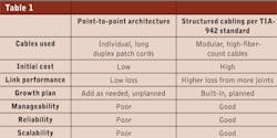
The traditional approach, and still the case for smaller facilities, has been to use individual, long patch cords for connections from servers to switch ports to storage. On a small scale, this has some appeal. It has low cost and it works. But as the needs and scope of the facilities grow, this point-to-point style of patch cord cabling can literally strangle a data center. Everyone has their examples of the cabling “spaghetti” that inevitably develops over time. Equipment changes and additions become difficult to manage. Individual circuit performance and reliability is compromised, causing frustrating intermittent outages. And eventually, available pathways and spaces become congested and choked, prohibiting further expansion. Increasingly a structured cabling approach is being deployed. It matches well with the modular nature of data centers, improving the manageability, reliability, and scalability. However, it does come at a higher initial cost and requires attention to link planning due to optical loss through multiple connector joints.
When designing and building a structured optical cabling system, early questions are inevitably: what fiber type to use, and how many strands? For fiber type, the answer has become rather clear; OM3 (laser-optimized 50-µm fiber) provides the lowest overall system cost (fiber plus transceivers) with sufficient performance for the link lengths of the largest facilities, and bandwidth for emerging protocols up to 100-Gbits/sec. Industry standards have also recently recognized OM4. It is essentially an OM3 50-µm fiber with higher bandwidth, enabling longer link reach for most applications. Because higher-data-rate applications generally have shorter link reach on a given fiber type, it is most important to plan the physical infrastructure with viable upgrade paths in mind.
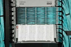
This front view of a 4U termination housing shows the importance of an up-front labeling system. To be useful, the labeling system must be kept up to date.
Fiber count requires some more thought and planning. It first depends on the switching architecture being used at the equipment cabinet level, at the end-of-row level, and at the aggregation level. It also depends on the type and density of equipment being used. While there is no simple single answer, it is possible to plan for and provision a given number of fibers per cabinet for a given class of equipment (e.g., blade center server racks). Two tips here can be helpful.
- Deliver the required aggregate fiber count to the row of cabinets, and build in a flexible approach to be able to distribute and redistribute those fibers among the cabinets over time.
- Plan the pathways and interconnect housings to accommodate future additions of fibers to and through the row over time. For example, the progression from 10-Gbit circuits to 40- and 100-Gbit circuits will most likely mean a change from 2-fiber circuits to 8- or 20-fiber parallel-optic circuits.
Depending on a facility’s technology upgrade timeline, it may not be desirable to over-provision fibers from the outset. But one should have the flexibility to group and use the available fibers as needed, and to add additional fibers in the future without a major rework of the whole infrastructure. A minimum recommendation is to provision 24 fibers for each server cabinet. With virtualization, blade-center density, Ethernet and Fibre Channel convergence, and 10-Gbit connectivity, valid cases can be made for 48 fibers and even 96 fibers per cabinet for high-availability servers.
The rest of this article will focus on the types and choices of components available from which to build a flexible structured cabling solution.
The perilous patch cord
The most basic and necessary component, patch cords, can be the key to an easily managed system or one that is complex and cumbersome. Common questions include the following. “Where is the other end of this patch cord?” “What [bad] happens if I should unplug it?” “How or where can I provision a new circuit?”
A strong labeling and documentation program is the first approach, but the sheer bulk of patch cords, particularly in high-density core areas, can frustrate any logical plan.
Port density has become limited by the transceivers that will fit on the face of a switch. The SFP+ transceiver with the duplex LC connector interface has shrunken the size and increased the density by twofold in recent years. Correspondingly, these small-form-factor connectors have driven down the cable size from a 3-mm diameter to 2 mm and lower. But now we have many more patch cords that are each less robust, and the prospect for problems resulting from bending and crushing becomes more of a concern. Fortunately, a new breed of resilient, bend-insensitive fiber is emerging to alleviate these concerns.
The 12-fiber MPO connector has grown in popularity and is adaptable to different data center needs.
An additional approach is to employ harnesses that bundle fibers from up to 6 patch cords into a single 3-mm cable. While increasing the durability, harnesses also greatly reduce the bulk of patch cords on the switch’s face, improving access and visibility as well as physical routing and management. The use of industry-standard 12-fiber MPO connectors—about the same size as one duplex LC—at one end of the harness can greatly improve the patching density and reduce the rack space needed for passive interconnects. The next generation of transmission rates using parallel optics, 40 and 100 Mbits/sec, will use this MPO connector right at the transceiver.
A housing’s importance
A structured cabling system necessarily needs connection points for crossconnection, interconnection, and aggregation from many end nodes into high-density, high-fiber-count trunk cables. Optical connectors are vulnerable points in a network and, as such, are appropriately protected in termination housings.
The two prime roles of a housing are to provide a point of administration and protection for the fiber joint. In general, passive termination housings take up valuable rack space, so doing more in less space is desirable. However, this should not be pursued to the point of sacrificing easy and reliable fiber access or the ability to maintain fiber’s management and organization. So the oft-maligned “sheet metal box” actually has a significant role to play if designed cleverly—packing the most fiber joints into the smallest amount of space, while preserving access and functionality.
A well-designed termination housing will exhibit the following attributes.
A robust strain-relief mechanism for each trunk cable entering the back of the housing. One sure way toA 144-fiber tight-buffered cable, which requires field termination, is approximately 0.92 inches in diameter. That is more than double the size of some available 144-fiber factory-terminated trunk cables.
As stated earlier, data centers are dynamic on the growth front. One false savings is to provide the bare minimum of housing capacity at the outset of a build. It will change over time. Factor in room for growth, and either provision excess fiber-termination capacity and/or leave open, designated rack space for the growth.
The right connection
Connectors are an increasingly important piece of the puzzle. Most connectors for data center applications are now factory-installed, whether it is on a patch cord or on a preterminated trunk cable. But the connector choice and its performance are key to providing “any-to-any” connections. The duplex connector is necessary for serial connections (transmit and receive) at a crossconnect and at equipment interfaces. The most common connector used today offering a small form factor and high density is the duplex LC. For interconnect points where fibers are being aggregated, a multi-fiber connector offers better density. The most popular is the 12-fiber MPO-style connector.
The progression toward 40- and 100-Gbit/sec network protocols is currently calling for parallel optics in place of serial connections, and MPO connectors are being specified and standardized for the future equipment interfaces. Another challenge for the cabling solution is to have a viable migration path from 10 to 40 to 100 Gbits/sec, as the same patching requirements will exist but the connector type will change. The good news is that 12-fiber MPO-terminated trunk cables that have become quite popular are adaptable to the needs without “rip and replace,” as long as fiber polarity management is built in and termination housings are designed with the necessary higher fiber counts in mind.
Connectors are also the “weak link” in the overall channel insertion-loss budget. As network protocols get faster, link-loss budgets are getting very tight and are dominated by allowable connector loss rather than fiber length attenuation. As a simple statement, the lower the loss of a mated pair of connectors, the better. However, for multi-fiber MPO-style connectors, each fiber in the 12-fiber array is equally important, so a maximum loss per fiber is the right metric to consider.
A more elaborate concern and consideration is modal noise introduced by connectors. It is not quite as easy to say that more connector pairs can be added up to the total allowable budget for connectors, without understanding the impact of modal noise. This is a complex issue that cannot be checked in the field, so make sure the connector supplier understands the issue and has completed the lab evaluation for quality assurance.
As a final point, a connector is intended to be mated with any other connector of the same kind (e.g., LC-to-LC, MPO-to-MPO) and likely, with different connectors during its operational lifetime. The resulting joint must be good every time with every different pairing. The way to ensure performance is with care, quality, and consideration of the connector endface geometry. These are attributes that are not often considered or specified because they are hard to see and measure in the field. With the right equipment, it is feasible to assess each and every polished connector in the factory before it is unleashed on the unsuspecting data center. Ask for this level of attention.
Fiber-cable construction
Until we see the advent of “data center wireless,” cables remain the necessary medium for carrying information from Point A to Point B. An irony with optical-fiber cables is that while the strands of glass are tiny, and the core light-carrying region is too small to be seen by the naked eye, the cable itself can be large, bulky, and inflexible (although compared to copper cables with the equivalent information-carrying capacity optical cables are trifling).
A brief history is worthwhile to understand past and future trends with cable designs. Optical fiber was first used en masse in outside plant applications. Cabling structures largely evolved from this need. When fiber use started to migrate indoors, a combination of three important factors shaped new designs.
- Required fiber counts were rather low with 6 to 12 being most common.
- Compliance with building fire-safety codes generally resulted in bulkier cable sheaths to inhibit flame spread and smoke propagation.
- Relatively short cable lengths and frequent termination created a desire for direct field connectorization.
As a result, tiny fibers were made larger to facilitate field handling and termination practices. Over the years, as optical communications has become more prolific indoors, fiber counts have increased, particularly so in the data center environment. Increased fiber count results in cables that are large, stiff, and generally unwieldy. So the user is faced with a tradeoff of one large cable or several smaller, easier-to-handle cables for a given fiber run of, say, core switching to a row of server cabinets. An allure of choosing several smaller cables can result in directly distributing the fibers to cabinets within the row, thereby losing the ability to easily and effectively manage the distribution of those fibers through the row over time.
The solution is to find high-fiber-count cables that still have the handling attributes of small cables. This is feasible with one of the key historical constraints removed: direct field termination. Due to the proliferation of optical cabling in a data center, it has become much less desirable to field-terminate cables. For larger projects, tens of thousands of individual fiber connectors can be involved, and this simply becomes an intrusive and unmanageable task as all elements of a data center build are coming to a close.
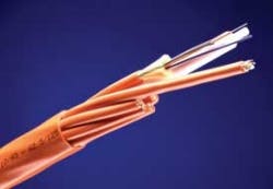
The trend has moved to factory-terminated cables. This trend creates a new challenge in that specific cable runs need to be engineered to length. Realistically there is a need for some over-length, which must be stored. So the drive for small-diameter, flexible cables is still key. Removing the field termination constraint allows the use of much-smaller ribbon and/or loose-tube fiber cable designs that are conducive to multi-factory factory-termination processes. Smaller-diameter cables permit more cables in cable trays, conduit, overhead and underfloor; they are lighter, more flexible, and they allow tighter bending for easier installation. The combination of small, flexible, preterminated high-fiber-count cables becomes a very useful and friendly tool for a plug-and-play style of deployment, while preserving the key design goal of cable-plant flexibility.
Good cabling is not just about keeping up; it is most desirable to keep ahead, neat, tidy, and organized. It is also desirable to facilitate reliable ongoing operations that enable, not inhibit, continual growth strategies.
A well-thought-out structured cabling plant becomes a valuable asset in the data center. Build in pathways and spaces, and designate unused rack space. Seek products that bring form and function, and allocate funding in your budget for them. It will be a sound investment in the long run.
Martyn Easton is manager of strategic alliances and Angela Lambert is manager of strategic accounts with Corning Cable Systems (www.corning.com/cablesystems).


