Encircled flux improves test equipment loss measurements

The new metric improves link-loss consistency by controlling mode groups during testing.
Seymour Goldstein, Fluke Networks
Encircled flux (EF) is a new metric for defining launch conditions on multimode fiber. It was developed by optical experts to reduce variability in link-loss measurements shown by different test equipment and to correlate test results to conservative launch-condition performances in Gigabit Ethernet fiber transceivers. Compared to previous launch conditions and standards, EF will greatly improve link-loss measurement consistency.
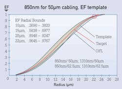
The circle in this template for 850-nm, 50-µm encircled flux, shown at 22 µm, indicates the area that most affects loss measurements.
The standards specifying multimode launch conditions have evolved over the last two decades. Simple mode filters (the process commonly known as wrapping fiber around a mandrel) have been replaced with near field measurements of optical power profiles, resulting in finely tuned “launch controllers” that provide EF-compliant testing in the field. The work done in standards groups has advanced the study and practical implementation of EF as the result of collaboration between test equipment suppliers, fiber and connector manufacturers, and cabling providers.
Which multimode reading to trust?
Multimode loss testing can be confusing because no one knows which tester is providing the “correct” reading due to variability in light-source launch conditions. Until the last few years, there was no need for a precise method and metric to define a predetermined launch condition from a multimode source.
Imagine this scenario. An installation team installs a fiber plant, tests each fiber, and delivers the results to the building owner showing that all fibers have passed a certification test for fiber link loss. For a typical fiber loss, the installation technician measures 2.0 dB using a light source and power meter.
The building owner then decides to spot check a few fibers using his own equipment, which includes a different light source. He gets a different result. He may measure 3.0 dB for the same link that measured 2.0 for the installation crew.
As either an installation contractor or a cabling-plant manager, do you have to imagine the above scenario, or has it actually happened to you? It has in fact happened to many.
Which source is right? It depends on several factors. First, it depends on the launch conditions of the light source. A light-emitting diode (LED)-based source might provide a different test result than a laser-based source. Second, it depends on the number of mode groups supported by the source and the test cord. Most importantly, it depends on which source most closely matches the network to be tested. The closer the launch conditions are between the test source and the network transceiver, the better the results will be.
Because optical power meters are calibrated and traceable, there is usually good agreement between various suppliers’ test instruments. However, while multimode light sources can be calibrated for optical output power, this is not necessarily the case for their launch conditions. The ideal situation is to use a source that closely matches the launch conditions of the transceiver; for Gigabit Ethernet transceivers that typically use vertical-cavity surface-emitting lasers (VCSELs), the most-similar launch condition mirrors that of EF. Consequently, by using test gear that is EF-compliant, one can be assured that a VCSEL-based transceiver will have similar link-loss (attenuation) characteristics. Testing to the EF standard is important because it tests the fiber link to the worst-case situation and almost guarantees good network performance.
Encircled flux defined
EF is a multimode launch-condition metric that serves several purposes. Its first intention is to reduce link-loss variation when using different light sources so test results are similar, independent of the supplier. This variation has been limited to ± 10% for link loss higher than 1 dB. EF was developed to keep up with components used in high-speed networks, e.g. 10/40/100-Gbit Ethernet. It was not until high-speed transmission over multimode fiber became a reality that EF measurements became important. High-speed 850-nanometer VCSELs and OM3 and OM4 laser-optimized wide-bandwidth fiber came together to create this “game changer.” EF targets 850 nm and 50-µm cabling because that is where the Gigabit Ethernet components are used.
Depending on the light source’s launch conditions and the number of mode groups the source and test cord support, two tests of the same fiber-optic link using different light sources may yield different results.
Fluke Networks and other experts developing international standards recognized that a simple mode filter was inadequate, and responded with a qualification template based on mode power distribution (MPD). MPD was the metric used to describe launch conditions within the International Organization for Standardization and International Electrotechnical Commission’s standard ISO/IEC 14763-3 Information Technology – Implementation and Operation of Customer Premises Cabling – Testing of Optical Fibre Cabling. The metric is now superseded by EF because it was found that channel or link loss consistency using sources compliant with MPD are insufficient to meet the tight loss budgets for Gigabit Ethernet.
Within the international standard ISO/IEC 61280-4-1 Fibre-optic Communication Subsystem Test Procedures – Installed Cable Plant – Multimode Attenuation Measurement, four different compliance templates are used for 850-nm and 1300-nm for both 50-µm and 62.5-µm cabling.
The figure on page 5 shows the template for 850-nm, 50-µm EF. The circle around the EF template at 22 µm represents the area that most affects the loss measurements. This is the area, along with the 20-µm control point, where mode control is most important. The equation of light intensity ratios along with near field measurement equipment constructs or builds the EF response.
How EF solves the problem
EF solves the problem by controlling the number of mode groups launched from the test cord. Consistency in launching repeatable mode groups is both an optical and geometric problem and is related to the launch wavelength, the initial launch condition (i.e., overfilled or OFL launch), the test cord’s fiber-core size, the fiber numerical aperture, the external mandrel, and other fiber properties.
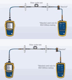
Commercially available today, launch controllers like those shown here (items 1 and 2 in the illustration) achieve encircled-flux compliance when coupled to any light source.
Because test cords are such an important part of EF compliance, suppliers and installers will have more-stringent requirements for providing high-quality reference-grade cords. For multimode fiber test cords, reference grade requires less than 0.l-dB insertion loss. By creating a tight standards-based template to which all test-equipment suppliers must adhere, the problem of consistent loss measurements using an EF-compliant source will be mitigated.
Limitations to compliance
Two primary factors, dual-wavelength field equipment and variability of fabrication process, may limit EF compliance.
Dual-wavelength field equipment. For ease of use and increased productivity, field test equipment is designed with a single optical port for both 850 and 1300 nm. The test set is coupled with a test reference cord wrapped around a single mandrel, where the mandrel must provide the desired launch condition for both wavelengths simultaneously. This setup may negate alignment of each individual source to its respective EF target and may produce a compromised alignment for each wavelength.
Alignment typically is performed by tuning to one wavelength, then checking the other for compliance. Using this approach with a single mandrel, alignment performed for one wavelength to meet EF may, on occasion, cause the other wavelength to exceed the EF template boundary.
Studies have shown that this is mostly the case for 50-µm cabling at 1300 nm. The figure on page 9 illustrates that both wavelengths cannot be made to reach their respective targets from a single port source. Because most high-speed networks are run at 850 nm and 50 µm, they are the most relevant specifications for EF.
Fabrication process and variability. A cost-effective factory process for EF tuning, assembly, and test is required. One such process might use a factory “standard” source when tuning test reference cords (TRCs) and mandrels for EF compliance. When this TRC/mandrel goes into the field it may not be perfectly interchangeable due to different physical variables that contribute to uncertainty. This implies that EF compliance can only be guaranteed at the time of factory fabrication.
Some factors that contribute to variation include the source wavelength and the fiber-core size. As the fiber size varies from 50 µm to 49 µm, for example, the number of mode groups supported is reduced from 19 to 18.
To mitigate this issue, it is recommended to use only the TRCs supplied by the test-equipment manufacturer. These test cords were used during the development of the test equipment, are required per the standards, and will give the best test results. As always, due to properties inherent in fiber optics, it is very important to keep connectors clean.
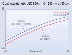
Dual-wavelength light sources have a shortcoming in that the 850- and 1300-nm wavelengths cannot both be made to reach their respective targets from a single port source.
When reviewing suppliers’ test gear, consider how the specifications for EF compliance are written. Because compliance is most closely related to operating high-speed networks that use VCSELs, this is another reason why the 850-nm and 50-µm specification is considered the most important. As with many product specifications, footnotes are common to explain the unique conditions under which the specification will be met. Also, be aware that all suppliers have similar constraints with their equipment.
Complying with EF
At this point, some installers might be asking themselves if they can continue using their existing equipment to conduct loss testing. If an installer wants to use a source that was slightly overfilled relative to the EF template target, the loss readings will be slightly pessimistic and one could have high confidence in a passing result. On the other hand, if an installer had to test Gigabit Ethernet cabling where loss budgets are tight, the EF standard becomes more relevant.
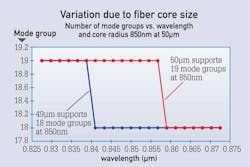
A core-size difference of one micron, from 50 to 49, reduces the number of modes supported from 19 to 18.
From the end-user customer’s point of view, there may be an expectation that test instruments already in the field can be retrofitted for EF compliance. External “launch controllers” that are EF-compliant when coupled to any light source are commercially available.
Encircled flux is a new multimode launch-condition metric that improves link-loss consistency by controlling the number of mode groups during the fiber-testing process. The current encircled flux launch conditions, using solutions such as launch controllers, are a great improvement over previous standards.
SEYMOUR GLODSTEIN is principal engineer at Fluke Networks’ media test business unit and manager of the company’s fiber-optic design center.

