Making the switch from 62.5- to 50-micron fiber

What to do, and what not to do, when opting for higher-bandwidth 50-micron multimode.
John Kamino, OFS
Multimode fiber systems continue to provide the most cost-effective cabling solution for data centers, local area networks (LANs), and other enterprise applications. Compared to singlemode fiber, multimode systems offer significantly lower costs for transceivers, connectors, and connector installation while meeting and exceeding the bandwidth and reliability requirements of the most demanding networks.
If you are designing a new short-reach installation, you will probably choose laser-optimized 50-micron (µm) OM3 or OM4 multimode fiber. These fibers preserve the systems-cost benefits over singlemode fiber by using low-cost 850-nm vertical-cavity surface-emitting laser (VCSEL) technology, are capable of 10-Mbit/sec through 10-Gbit/sec operation, and will support upcoming 40- and 100-Gbit/sec transmission speeds.
But if you are upgrading an existing system, many of which have 62.5-µm multimode already installed, should you stick with 62.5-µm? Or can you go with the higher performance of 50-µm OM3 or OM4 fiber? This article highlights the things you must consider when upgrading an existing 62.5-µm system.
Why two fiber sizes?
The numbers under discussion—50-µm and 62.5-µm—refer to the diameter of the fiber’s core, through which light signals are transmitted. The first optical fibers, deployed in the 1970s for both short- and long-reach applications, were 50-µm multimode fibers. In the early 1980s, singlemode fiber replaced 50-µm fiber in longer-distance installations. However, 50-µm multimode continued to be more cost-effective for short-reach interconnects, such as building and campus backbones, up to 2,000-meter distances.
But as data rates increased, 50-µm fiber could not support 10-Mbit/sec rates over the 2-kilometer distances required by some campus installations. Not enough power could be coupled from the light-emitting diode (LED) sources in use at that time into the 50-µm core to support these link distances.
62.5-µm multimode fiber was introduced in 1985 to solve this problem. It could capture more light from a LED in its larger core, and 2-km campus links operating at 10 Mbits/sec were easily supported. Also, the larger-core fiber was easier to cable and connectorize. It became the most commonly used fiber for short-reach enterprise applications in North America.
Today, as data rates surpass 10-Gbits/sec and lasers have replaced LEDs, 62.5-µm fiber has reached its performance limit. 50-µm fiber offers as much as 10 times the bandwidth of the 62.5-µm fiber. What’s more, improvements in technology have made 50-µm fiber easier to use.
Multimode fiber choices today
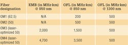
To consider making the switch from 62.5-µm to 50-µm multimode, it is important to first understand the terminology used to designate the various performance grades of multimode fiber. In each of these designations, “OM” stands for “optical multimode.” For example, OM1 is the designation for fiber with 200/500 MHz∙km overfilled launch (OFL) bandwidth at 850/1300 nm; this typically is 62.5µm fiber. OM2 is used for fiber with 500/500 MHz∙km OFL bandwidth at 850/1300 nm (typically 50-µm fiber).
More-recent additions are OM3, for laser-optimized 50-µm fiber having 2,000 MHz∙km effective modal bandwidth (EMB, also known as laser bandwidth) at 850 nm (designed for 10-Gbit/sec transmission), and most recently OM4, for laser-optimized 50-µm fiber having 4,700 MHz∙km EMB at 850 nm, designed for 10-Gbit/sec transmission over longer distances.
It’s also important to note that for next-generation 40- and 100-Gbit/sec Ethernet, only OM3 and OM4 fibers are included in the draft standard as supported (multimode optical fiber) media. OM1 and OM2 fibers are not supported media types.
The latest offerings in multimode fiber are 50-µm bend-optimized products. These fibers offer all the advantages of high-bandwidth laser-optimized multimode fiber, with the added advantage of lower bend sensitivity. Traditional 50-µm multimode fibers can be sensitive to tight bends, leading to high link loss that could exceed the system loss budget. New bend-optimized multimode fibers offer extremely low bending loss at both 850 and 1,300 nm. These fibers can be bent down to a radius of 7.5 mm (almost ¼-inch) with less than 0.2 dB added loss at 850 nm. At a 15-mm radius (~½-inch), the added loss is less than 0.1 dB—up to a 10x improvement in bend loss compared to traditional multimode fiber, significantly diminishing the threat of added loss created by tight bends.
Upgrading a 62.5-µm network
The primary considerations for an upgrade or extension of an existing 62.5-µm network are:
- the required transmission speed (now and especially in the future),
- link distance,
- ease of cable replacement, and
- cost of cable replacement.
If you are running Gigabit Ethernet (1-Gbit/sec), then legacy 62.5-µm fiber will transmit a distance of 220 to 275 meters, depending on its bandwidth rating. But at 10-Gigabit Ethernet (10-GbE; 10-Gbits/sec), they will only support 26 to 33 meters. If your network will not need to support 10-GbE at distances greater than 25 meters, then you may be able to stick with 62.5-µm fiber. It is important to note, however, that most 62.5-µm fiber has not been measured for laser bandwidth, and some legacy fiber may have difficulty supporting even this short distance.
And if you want to transmit longer distances over 62.5-µm fiber, you will be forced to use much-more-expensive 1,300-nm transceivers that will operate over multimode or singlemode fiber. These transceivers cost significantly more than 850-nm multimode devices, because the 1,300-nm optoelectronics package is the far more complex of the two.
If you are considering extending your network by installing additional 62.5-µm fiber, you need to carefully review your future network plans. If you plan to upgrade your network speed to 10-Gbits/sec in the future, recabling with laser-optimized OM3 or OM4 fiber would be a wiser choice.
Measuring laser bandwidth
As previously stated, 62.5-µm fiber provides limited support for 10-Gbit/sec transmission, so it generally is not measured for laser bandwidth (EMB). Typically, only 50-µm fibers are measured for EMB. To verify bandwidth of 62.5-µm fiber, the traditional OFL bandwidth measurement method is used.
For 50-µm fibers, EMB is ensured by using a method called Differential Mode Delay (DMD). This DMD test is required by standards to verify 10-Gbit/sec performance, and involves scanning the fiber’s core in small increments to see how the signal travels in various regions of the core.
Once the DMD test is conducted and a DMD “profile” is obtained, the standards allow two methods to disposition the fiber. One is the DMD Mask method, and the other is the Effective Modal Bandwidth Calculated (EMBc) method.
The DMD Mask method provides direct verification of the fiber’s DMD performance using a set of clearly defined DMD masks and templates that are overlaid on the DMD profile. This technique provides flexibility in applying more-stringent DMD performance criteria in certain regions of the fiber, including the 0-5µm center region.
The EMBc method involves complex calculations involving 10 weighting functions to represent the wide variety of 10-Gbit/sec VCSELs available on the market. Theoretical in nature, this technique does not, in OFS’s opinion, provide the scrutiny on fiber quality and performance that the DMD Mask technique does. The EMBc method puts little emphasis on the 0-5µm region of a fiber’s core. Though standards allow both testing methods, OFS advocates the DMD Mask method.
Mixing 50- and 62.5-µm
If you decide to add 50-µm fiber to an existing 62.5-µm infrastructure, connecting 50-µm directly to 62.5-µm is generally not recommended. The difference in core sizes could cause high loss when transmitting from the 62.5-µm into the 50-µm fiber. Also, the bandwidth of 62.5-µm fibers is typically much lower, further degrading system performance. Even if a low-speed application operates over a link made up of mixed fiber types, upgradeability will be severely compromised.
This elevated-loss problem occurs when transmitting from the larger (62.5-µm) to the smaller (50-µm) core. It is comparable to a 4-inch water pipe connecting to a 3-inch pipe; there is no problem going from the smaller pipe to the larger one, but going in the opposite direction can lead to a lot of lost water (or in this case, light).
The amount of connection loss you could experience is about 4 dB for a LED-based system, which fills the entire core of a 62.5-µm fiber, and anywhere from 0 to 4 dB for a VCSEL-based system, which only fills a portion of the core.
Because most optical-loss test sets use LEDs, you should plan for the worst and assume you will see a 4-dB loss in one direction. If your link budget can tolerate this additional 4-dB loss, then you can get away with connecting 50-µm directly to 62.5-µm.
The better scenario is to separate 50-µm from 62.5-µm with active electronics, such as a switch, router, or simple media converter.
Mixing of 62.5-µm and 50-µm fiber is not recommended unless an electronics interface is inserted into the link. If 10-Gbit/sec speeds are being installed, 62.5-µm fiber will only be able to support extremely short links, and replacement is recommended.
John Kamino is product manager, multimode fiber with OFS (www.ofsoptics.com).

