Taking your network infrastructure to the next level
User cases show the benefits of patching switches, cluster designs.
by Ben Carmi, RiT Technologies
In the last couple of decades, technology has completely metamorphosized. We have gone from the fax machine and WordPerfect (not so long ago), to iPhones, iPads and more. Software, gadgets, and other technology belonging to the so called “logical layer” have advanced so dramatically that one does not have to be in the office to access email, verify information or talk to customers. We are now living in an “anytime, anywhere” information era. Unfortunately, however, the communication room, the heart of an organization’s network, or the “physical layer,” has not managed to maintain the same pace. Without adequate planning, the room becomes one big mess with all the building’s cabling ending up in complete tangles, looking like a big obstacle course.
Contrary to popular belief, a clean and neat physical-layer environment is attainable. RiT Technologies originally pioneered the concept of patch panels with patching switches, based on its patented Patching Switches technology, which modified communications rooms. A new approach based on the patching switches concept and technology is called the cluster design. The solution for structured cabling actually requires up to 70 percent fewer patch cords per installation. This is significant considering the patch cord spaghetti, resulting from countless patch cords connecting to different patch panels. The consequences of fewer patch cords include: a simple environment, a reduction in maintenance and downtime and even a decrease in power consumption due to less-dense infrastructure, making it considerably cooler and protecting the environment.
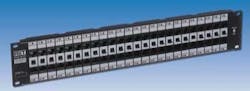
The Smart ClasSix 48-port patch panel incorporates RiT Technologies’ patching switches technology.
Figuring out the “bird’s nest”
In standard patch panel installations, the communication room starts out very neat, organized and clean. Over time however, as new equipment is added, the situation changes. The room becomes increasingly cramped and more difficult to keep organized. In an organization with thousands of users, for example, the communication room is so challenging that any small patching required turns into a major hurdle. The network personnel are petrified to touch just one patch cord in case another five are unintentionally disconnected. In today’s reality where business continuity is super critical, the consequences of this can be dramatic. When using patch panels with patching switches however, the situation is just the opposite. The room remains organized, easily manageable, and aesthetically neat and tidy. As the IT manager becomes more accustomed to the system, the more effective is its implementation and the more impressive its results.
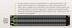
Mechanical patching switches exist between the two rows of a 48-port patch panel. Horizontal cables from the outlets are terminated on the upper row, while the active equipment is represented on the lower row of the patch panel. When the network personnel want to connect the first port, for example on the upper row to the first port on the lower row, they only need to push up the patching switch and the ports are connected. There is no more need for a patch cord.
Further enhancing the flexibility of the installation, the RJ-RJ model can be used. In this model, instead of using a termination block on the back of the panel and terminating pigtails, there are RJ-45 sockets to connect regular patch cords. This saves time and labor costs when representing the active equipment.
Designed for both unshielded twisted-pair (UTP) and shielded twisted-pair (STP) environments, patch panels with patching switches are available for Category 5e and Category 6. More recently, a new patented switch patch panel for Category 6A was introduced. The panel is part of a complete high-performance solution for Category 6A, which offers outlets, cables, patch cords and panels, including a unique solution for UTP environments.
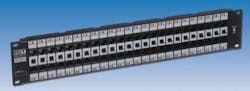
Users of patch panels with patching switches only need to push up the patching switch to connect ports. The technology eliminates the need for mess-inducing patch cords.
A large international news agency discovered the benefits of this type of patch panel with patching switches, offered by RiT Technologies. At one of the agency’s regional bureaus with 600 users, each requiring at least one data and one voice port, the customer reported a significant reduction in the amount of patch cords used. Instead of using the typical minimum of 1,200 patch cords, it uses only 60 patch cords. That is five percent of the number of cords you would expect to find in a regular installation.
Designing a cluster
A typical cluster should be able to expand itself dynamically and transparently. Many systems use clusters to achieve high availability, load balancing and high performance. The Cluster Design technology is no different. It is based on RiT’s patching switches and PatchView Intelligent Infrastructure Management (IIM) Solution. Brought together, they provide a powerful solution for high-speed, quality based real-time manageable infrastructure. With patch cords only needed to reassign ports, most of the channels are connected by the patching switches.
Suitable for any installation, it is modular and assumes the following: typically users will use at least two kinds of port outlets, one data port and one port for voice or telephone, and there are usually spare or reserved ports for future use.
For example, in one medium-sized organization, every user has a six-port outlet. The “typical user” uses two data ports and one voice port. The other three are reserved for future growth. The Cluster Design installed features a Category 6, 48-port patch panel with patching switches. The patch panel works with switches that connect the corresponding upper and lower port (when the switch is in the upper “on” position). This creates a link between the service and the outlet port. Each one of the six-port outlets is represented vertically in a separate patch panel. The vertical field forms a “cluster” that supports 48, six-port outlets.
In more complex installations, a “mirror” cluster design proves to be beneficial for the customer. In this design, the lower half of the rack is in fact a mirror picture of the upper one. This ensures that in the future, additional services can easily be added. If a situation occurs in which patch cords are in fact required, this design guarantees that they will be shorter, and the amount kept minimal. The size of the cluster is further determined by the number of outlet ports the user possesses. Depending on the use of optional panels, a 40-U rack can fit a cluster and a half, with every cluster being between 22-U and 26-U high.
One step further
RiT’s patch panels with patching switches, when used in conjunction with RiT’s PatchView IIM solution, offer valuable connectivity information about the entire network. PatchView enables real-time, centralized management and troubleshooting for even the most dispersed networks. LED indicators on panels identify any two ports patched together and enable 100% accurate moves, adds and changes (MACs). It also offers distinctive automated detection capabilities, LED-guided connections, and web-based remote maintenance capabilities.
With RiT’s Automated Provisioning Tool, the MAC process is further enhanced. IT managers can assign system and network resources and privileges to users in a fully automated environment. MACs occur effortlessly without the hassle of going backwards and forwards from the desk to the field to make sure the installation is correct. With highly advanced workflow, database and integration capabilities, PatchView offers the ability to automatically collect and analyze all the necessary data, such as space requirements, power and cooling, connectivity and switch port configurations. It also calculates the optimal resource allocation and produces a multi-team work order that is then tracked until it is fully completed.
Return on investment
An IT manager of a large data center in Asia appreciated these technologies when prospective customers came to visit. The prospect was impressed to see the technology, as well as the organized and clean the physical environment. “This certainly helps us win new accounts,” he said. “This alone ensures a quick ROI on the technology implementation.”
Ben Carmi is vice president of product management and business development at RiT Technologies (www.rittech.com).
Past CIM Articles

