Compatibility issues with bend-insensitive and standard multimode
Lab testing indicates risks associated with mixing bend-insensitive and standard multimode fiber
By Rick Pimpinella, Bulent Kose and Brett Lane, Panduit
The increasing demand for higher-speed data transmission within the data center and premises networks has led to the wide deployment of multimode optical connectivity. To meet performance and reliability requirements, the optical specifications on the components have also become more stringent. For high-speed optical networks using laser-optimized OM3 and OM4 multimode fiber, it is more critical than ever for network operators and designers to understand the attributes of the various performance grades of passive fiber-optic components that make up the network so that they may employ the most cost-efficient solutions that meet their needs today and in the future.
In order to ensure that optical networks operate effectively and reliably, it is fundamental that the optical fiber meets the necessary bandwidth requirements and that the total optical loss, or insertion loss (IL), is below the allowable limit required by the application. The two sources of IL within optical networks are: 1) loss at connector interfaces, and 2) loss, or attenuation, within the fiber itself. The IL limits for 10-, 40- and 100-Gbit/sec Ethernet are in the table on page 32.
The combination of eroding insertion loss budgets and increased demands for complex network architectures with many connector interfaces has triggered several fiber and connectivity suppliers to develop improved connectivity and fiber products that allow network architectures to cope with these trends. Specifically, several connectivity suppliers now offer low-loss, or optimized, passive fiber-optic components such as connectors, cassettes and patch cords that allow them to implement complex networks with numerous connector interfaces while still meeting the maximum connector loss budget.
Moreover, although the intrinsic fiber attenuation has not been reduced significantly over the past many years, recent advancements in fiber production have delivered extra headroom by significantly improving attenuation levels under tightly bent conditions, even in those cases in which the fiber is unintentionally subjected to bends smaller than that allowed with the ANSI/TIA-568-C.0 premises cabling standard. This article reviews how this new type of laser-optimized multimode fiber, often called bend-insensitive or bend-optimized, integrates into today's data center and premises network.
Achieving bend-optimization
It is well known that in order to produce a fiber with improved bend performance, it must be made to more tightly confine the light within its core region. This modification allows more of the light to meet the conditions necessary for total internal reflection as the fiber is bent. Enhanced optical confinement is accomplished by simply increasing the effective difference in the index of refraction between the core and cladding regions. This is typically accomplished by introducing an index depression, or trench, in the cladding region close to the fiber core.
The illustration on page 33 shows a schematic refractive index profile for standard multimode fiber and bend-optimized multimode fiber, showing that the effective difference in refractive indices between the core and cladding for the bend-optimized multimode fiber is greater than the effective difference in refractive indices between the core and cladding for standard multimode fiber. The depth, width and location of the trench and the index profile of the bend-optimized multimode fiber core vary from supplier to supplier.
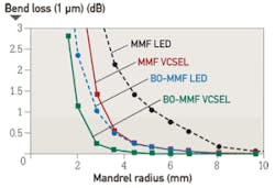
The average bend-loss performance of standard and bend-optimized multimode fiber samples are shown in the graph above. Measurements were performed using both a light-emitting diode (LED) light source, which generally illuminates the entire fiber core and corresponds to how links should be measured during link certification, and a vertical-cavity surface-emitting laser (VCSEL) light source, which only illuminates the central part of the fiber core and corresponds to how links will be illuminated during normal operation.
Because only the LED significantly illuminates the outer portion of the fiber core, nearest the index depression in bend-optimized multimode fiber, the bend-loss performance improvement between standard and bend-optimized multimode will be much greater during link certification measurements made with an LED than during normal operating conditions that use VCSEL sources. It is also important to recognize that there will be no performance improvement realized by either an LED or VCSEL source if the cable maintains the 568-C.0 bend radius specification of 25 mm.
Because the bend-optimized fiber allows a greater amount of light to meet the conditions necessary for total internal reflection (i.e. rays with larger angles), light emerging from bend-optimized multimode fiber will have a larger angle on average than light emerging from standard multimode fiber. The parameter that characterizes the maximum divergence, or acceptance, angle of light from or to a fiber is called numerical aperture (NA). Therefore, the NA of bend-optimized multimode is generally expected to be greater on average than the NA of standard multimode. A thorough sampling across multiple fiber manufacturers revealed that the average NA increased from 0.199 for standard multimode fiber to 0.207 for bend-optimized multimode fiber.
Although this moderate increase in NA appears insignificant, in some situations the optical loss across an optical fiber interface (e.g. connector) is dependent on the differences in NAs of the fibers. In the case that light fully populates the fiber core, such as when illuminated with an LED, and is coupled from a fiber with a higher NA into a receiver with a lower NA, the light will diverge at an angle larger than the acceptance angle of the receive fiber. This will result in some light being lost (into the cladding), and the interface will have loss proportional to the NA difference (ratio) between the two fibers.
Consequently, increased loss may be realized when light travels from bend-optimized multimode fiber into standard multimode fiber. In fact, the expected loss across a bend-optimized fiber with an NA of 0.207 and a standard fiber with an NA of 0.199 is 0.34 dB, which is a significant portion of the overall IL budget. In the case that light travels from a fiber with a lower NA into a receiver with a higher NA, or light does not fully illuminate the fiber core, no loss resulting from the difference in fiber NAs is expected.
NA loss measurements
To predict the NA loss that would be realized during link certification measurements of an optical channel with bend-optimized and standard fiber interfaces, a series of standard IL measurements were performed on selected bend-optimized and standard fibers. Fiber samples from several fiber manufacturers were selected with a wide range of NAs in order to provide not only a typical NA loss from fibers with average NA, but also provide an upper and lower limit of NA loss that may be expected when connecting dissimilar multimode fiber types without knowledge of NA differences. Several fibers were selected of each fiber type–some with an average NA, some with a low NA and some with a high NA. The following table summarizes the samples used for this experiment and the theoretically expected NA loss from each connection.
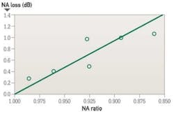
The measurement data is shown in the chart above. Each data point represents the average of the NA losses for a set of fibers for each NA combination. From this data, connecting dissimilar fiber types with average NAs confirms the theoretically predicted NA loss of approximately 0.40 dB. Additionally, the upper and lower limits of NA loss were measured to be 0.28 dB and 1.06 dB. Although these average and extreme NA losses are fairly well correlated with the theoretically predicted NA loss, other measured values deviate significantly from the theoretically predicted value. This suggests that factors other than NA, such as core diameter, index profile, and mode structure also significantly influence the loss when connecting bend-optimized and standard multimode fiber. As a result, the light does not couple with 100 percent efficiency between fibers and therefore an additional mode coupling loss must exist.
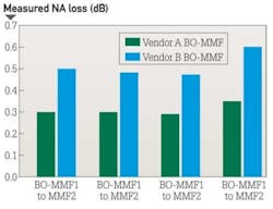
In fact, in the case that bend-optimized fiber samples with the identical NA but manufactured from different suppliers were connected to standard fibers, with NA equal to 0.200, the NA loss differs significantly from vendor to vendor. The average NA loss from Vendor A bend-optimized interfaces nearly exactly matched the theoretical NA loss of 0.30 dB, while the average NA loss from Vendor B bend-optimized interfaces was much higher at 0.51 dB. As expected, the bend-optimized fibers from Vendor B were found to be more bend-tolerant than those from Vendor A.
In addition to realizing unidirectional NA loss, an increase in the modal noise penalty may also result when connecting bend-optimized and standard multimode fiber. Modal noise is a power penalty related to the reduction in the signal-to-noise ratio (SNR) of the optical signal. For high-speed networks employing VCSELs, if a connector selectively attenuates higher-order modes as a result of NA mismatch or a lateral offset between fiber cores, then fluctuations in the power distribution (spatial speckle pattern) results in fluctuations in connector insertion loss. This fluctuation is seen by the detector as an increase in noise, thereby reducing the SNR and therefore, signal quality.
The maximum allowed power penalty for modal noise is currently specified in 10GBase-SR to be 0.3 dB. Both NA loss and mode coupling loss can increase the mode-selective loss (filter aperture) at a connector interface resulting in an increase in modal noise. Considering the overall power budget for 10G/40G/100G Ethernet is 1.5 dB (or 1.0 dB for OM4), any increase in modal noise may compromise system reliability.
In conclusion, inconclusive
As part of our review of how bend-optimized multimode fiber is integrating in today's data center and premises network, we measured the loss between bend-insensitive and standard multimode fibers to quantify the expected additional loss during certification of mixed-fiber links. These additional losses were measured to be as high as 1 dB, and can be a significant portion of–or even actually exceed–the total optical power budget for today's high-speed networks. For a channel link that contains several bend-optimized fiber and multimode fiber interfaces, which have large NA differences, the NA losses may be additive and further inhibit system certification.
Furthermore, although NA loss alone is unlikely to detrimentally influence system performance, it may be very difficult, if not impossible, to determine if excessive channel loss is due to NA differences or other conventional sources of loss, such as macrobending or dirty/damaged components. One strategy to account for this loss would be to require bidirectional loss measurements of individual optical interfaces.
During the most recent meeting of the TIA TR-42.12 Optical Fibers and Cable Subcommittee a vigorous debate included many of the topics discussed in this article and others, including increased NA loss, mode coupling loss, modal noise (which may negatively impact system performance), the validity of other standardized fiber test procedures for fiber core diameter, fiber bandwidth and link attenuation (encircled flux). The subcommittee authorized the formation of a task group to study the technical compatibility of bend-insensitive multimode fiber with current multimode fiber standards.
Based on our internal analysis and the present uncertain position within the standards community, we have concluded that the performance risks of mixing bend-optimized and standard multimode fiber types in high-speed optical channel links exceeds any benefit. To ensure that total optical loss across data center and premises networks remains below the allowable limit, Panduit recommends adhering to standards-based radius-control methods and the use of one fiber type throughout the channel link, which includes cabling and patch cords. This approach enables network stakeholders to reliably deploy complex network architectures, meet stringent IL budgets and ensure optimal system performance within current standards-based network architectures and testing methods.
Some manufacturers support this effort; others minimize its importance. Until the TIA subcommittee work on these issues is complete, we recommend that these two fiber types should not presently be mixed.
Dr. Rick Pimpinella is a distinguished engineer, Bulent Kose is a research engineer and Dr. Brett Lane is a fiber research manager with Panduit (www.panduit.com).
Past CIM Issues
