The facts about bend-insensitive multimode fibers
Reports meant to cause alarm about the medium's compatibility with other fibers are bending the truth.
By Jeffrey Englebert, Peter Pondillo and Ravi Yekula, Corning Optical Fiber
Bend-insensitive multimode fiber (BIMMF) has an innovative core design that enables it to significantly reduce macrobend loss even in the most challenging bend scenarios. This article discusses how BIMMF is fully compliant with the OM2, OM3 and OM4 standards for laser-optimized fibers and is also backward compatible with the installed base of 50-μm multimode fibers.
Not all bend-insensitive multimode fibers are created equal. Differences in designs of BIMMF result in differences in performance(s). Concerns have been raised regarding the full backward compatibility/standards compliance of bend-insensitive multimode fibers. Most of these claims reflect a misunderstanding of the performance characteristics of BIMMF and are made without supporting data. This article provides the necessary data and theory to debunk these myths and ensure end users can feel confident in the performance and capabilities of systems built with BIMMF, as well as its compatibility with existing multimode fiber systems.
Different designs and performances
BIMMF has an innovative core design that incorporates a graded-index core profile combined with a specially engineered optical trench. This trench enables it to confine the modes that propagate within the fiber core, even in the most challenging bend scenarios. The design of a proper bend-insensitive multimode fiber that meets the specifications of a standard multimode fiber poses a unique challenge. BIMMF needs to be designed to provide reduced macrobend loss and at the same time take into account key design parameters such as core diameter, numerical aperture and bandwidth.
BIMMF profiles pose a complex design challenge. Profile parameters must be carefully selected to ensure all key attributes satisfy all relevant industry standards. Bandwidth is a key parameter for multimode fibers and the graded-index profile remains a key driver to achieve high bandwidth. Any deviation from the optimum profile results in reduction of bandwidth of the multimode fibers. Few manufacturers are able to produce high-bandwidth multimode fibers that offer exceptional bend capability that also meet all of the specifications of traditional multimode fibers. Inappropriate trench location can result in delay errors of the higher-order modes, and this can significantly impair bandwidth performance. Locating the trench too far from the fiber core can result in failure to comply with fundamental industry standards. The fiber's trench location must be carefully engineered to ensure superior bandwidth and macrobend response while maintaining industry standard requirements for core diameter, numerical aperture and chromatic dispersion.
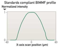
The figure on page 37 shows an example of a standards-compliant high-bandwidth bend-insensitive multimode fiber's alpha profile. The core diameter of this fiber, as defined by both the 80/10 fit and the 2.5 percent threshold, falls within industry standards. A well-designed BIMMF should comply with both 80/10 fit and 2.5 percent threshold core diameter definitions. The 2.5-percent threshold method defines the core diameter at the point at which the power is reduced to 2.5 percent of the normalized power. A fiber that adheres to the 80/10 fit, fits the data from 80 percent normalized power to the 10 percent normalized power to a power-law equation. The core diameter is defined at the point at which the extrapolated equation intersects with the "zero normalized power."
The near fields for two other BIMMFs are presented in the figures on page 38. The near field provides the best representation of where power actually resides in the fiber. Both the 80/10 fit and the 2.5-percent threshold are applied to the measured near field, which is a plot of measured power as a function of radial position in the fiber. The near field of the fiber in the graph on the left-hand side of the figure has tails that extend well beyond the core boundary. Additionally, the near field in the graph on the right-hand side of the figure has localized peaks near the core boundary. As a result of these features, both of these BIMMFs have core diameters that are higher than approved industry standards for a 50-micron fiber.
It is easy to understand how the fibers presented in the figure on page 38 might pose interoperability issues with either standard multimode fiber or well-designed BIMMF, and also raise significant issues relative to OM3/OM4 selection criteria. The near field profile suggests the presence of additional power in the higher-order modes. The additional power could affect interoperability when these fibers are coupled in homogeneous and heterogeneous lengths. Furthermore, the additional power in this radial could affect the application of differential mode delay (DMD) mask templates. Several of these templates have lenient outer masks that may not appropriately account for the additional power in this region.
The alpha profile of a standard-compliant high-bandwidth bend-insensitive multimode fiber is shown here. The profile's "smoothness" is a result of it falling within industry standards for the 80/10 fit and the 2.5-percent threshold.
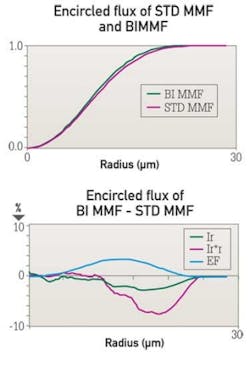
The design of BIMMF tightly confines the higher-order mode groups to minimize attenuation due to small radius bends. One potential side effect of this is a change in the light-capturing characteristics of the fiber. Any significant changes in these characteristics could affect the functionality of attributes associated with OM3/OM4 fiber selection, such as EMBc weights and DMD mask templates. The most direct method to assess the impact of the fiber design on transmitter launch characteristics is to assess the response of encircled flux (EF) to varying launch conditions. EF is the percent power within a given radius launched by a transmitter into a multimode fiber core. Differences in EF between a properly designed BIMFF and standard multimode fiber should fall within the typical repeatability of the measurement. The figure below shows examples of EF measurements of standard MMF and BIMMF, and the differences in EF with three disparate launch conditions that span the range of power distributions seen in commercially available VCSELs. The differences in typical EF that were obtained with these two different fiber types were typically within 1 percent under all launch conditions. This variation is within the typical variability of EF measurements. Since the EF values are similar, the EMBc weight functions will also be similar.
These near fields for two non-compliant bend-insensitive multimode fibers show, in the graph on the left, tails that extend well beyond the core boundary and, on the right, localized peaks near the core boundary. As a result, both of these fibers have core diameters higher than approved by industry standards.
Other BIMMF designs did not fare as favorably. As indicated in the other figures, these BIMFF designs can yield significantly different EF values of up to 4 percent with the same launch condition. Furthermore, the variation in EF values is evident at multiple launch conditions. This is again proof that certain BIMMF will be subject to significant variations in power distribution. These variations could result in issues with fiber selection criteria, particularly for users of the DMD mask due to the lenient outer mask requirements on many templates. The variation in power distribution suggests there could be significant interoperability issues between standard MMF and other BIMMF.
Insertion loss and interoperability
A well-designed BIMMF has minimal insertion loss when employed with either standard MMF or other well-designed BIMMF products. In many cases the loss associated with a homogeneous splicing of BIMMF is superior to that of homogeneous splices of standard MMF. The table on page 36 shows the splice loss results of several BIMMF produced with different manufacturing processes. Clearly, a well-designed BIMMF provides equivalent loss performance to that of a standard MMF.
These graphs show encircled flux (EF) measurements of standard and bend-insensitive multimode fibers under three launch conditions that span the power-distribution range of commercially available VCSELs. The differences in EF, typically within 1 percent under all launch conditions, indicate the bend-insensitive multimode fibers tested were properly designed.
Connectorization studies also validate that the insertion loss of a well-designed BIMMF is comparable to standard MMF for coupling of homogeneous fibers.
The encircled-flux measurements on other bend-insensitive multimode fibers yield different results. Here, as shown in the graph on the bottom, the variation in EF values is evident at multiple launch conditions. These results indicate that certain bend-insensitive multimode fibers will be subject to significant variations in power distribution.
In summary, a well-designed BIMMF complies with all relevant industry standards and adheres to the following.
BIMMF OM2, OM3 and OM4 multimode fibers are fully compliant and fully backward-compatible with all relevant industry standards.
BIMMF is fully backward-compatible and may be used with the existing installed base of 50/125-μm multimode grades including OM2, OM3 and OM4.
BIMMF may be spliced or connectorized to conventional 50/125-μm fiber types with commercially available equipment and established practices and methods; no special tools or procedures are required.
BIMMF not only meets all relevant macrobend standards, but sets a new level of bend performance.
Jeffrey Englebert is manager of product engineering at Corning Optical Fiber's Center for Fiber Optic Testing. Peter Pondillo is manager of standards engineering and Ravi Yekula is product line manager, multimode fiber with Corning Optical Fiber (www.corning.com/opticalfiber).
Past CIM Issues


