Covering a 40k-sf warehouse with one access point
December, 2012 Issue of Cabling Installation & Maintenance Magazine
The capabilities of waveguide systems are now available in more-affordable technology.
By Charles Becker, Wireless Expressways
One of the most difficult indoor spaces to fully illuminate with wireless (WiFi) signals is the typical large, multi-aisle warehouse. The product racks between aisles look like variably reflecting and partially leaking walls to the passage of 802.11b WiFi signals in the 2.4-GHz industrial, scientific and medical (ISM) band. Many WiFi companies suggest dividing the floor area by 4,000, or even 3,000, to estimate the number of access points needed—assuming that “RF (radio frequency) overkill” will be necessary to get signals through products on racks.
Even if an extensive site survey is performed in a facility and multiple access points are deployed in what seem to be the best locations, areas of weak or no signal coverage can occur as products are added or changed on rack shelves—which, unfortunately, is what warehouse owners want to do. What’s needed is a new yet proven antenna strategy that is optimized for warehouse WiFi coverage.
Relying on the passage of signals through products on rack shelves and installing large numbers of access points (APs) are no longer necessary. Warehouse WiFi installations, if designed with the right technology, can result in very efficient radio communications systems that will cover all user areas with high-level, high-quality WiFi signals while significantly reducing the required number of APs.
Aisles in warehouses should be treated as “RF caves.” The method of supplying signals to client devices in these aisles needs to ignore all racks and instead, should illuminate each aisle separately. An access point with an attached antenna could be placed at the end of each aisle. That is not only expensive, but has the additional problem of causing co-channel interference, starting with the fourth aisle, if the system uses the three available 11-Mbit/sec non-overlapping 802.11b channels.
The ideal design would make use of up to three access points, all on separate channels, simultaneously covering all of the warehouse work areas. Highly directional antennas, with radiation patterns matched to the aisles, are also very desirable for illuminating each aisle instead of currently used, omnidirectional, low-gain “rubber ducky” antennas, as they are called. Directional antennas can not only focus transmitted signals from APs to clients in each aisle, but also can concentrate signal levels from clients to an access point. Antennas on an access point that “see” (directly illuminate) client devices in each aisle, while ignoring undesirable directions, will provide and maintain highly reliable radio associations, low error rates, fast responses and few roaming events for a trouble-free warehouse system.
New technology
If all the aisle antennas could be fed from a common (single) access point, or one or two more for backup, and each aisle employed a directional antenna pointed down its axis, the need to try to propagate signals through the clutter of products on rack shelves would be eliminated.
But how do you connect all those aisle antennas together along a warehouse cross-aisle that may be hundreds of feet long, without high loss of signals in the process? It has been known for quite a while that the type of transmission line with the lowest loss is metallic waveguide. Indeed, waveguide is regularly used for long runs up towers to dish antennas in point-to-point microwave links and also sees frequent use in radar and military systems. The cost of waveguide, however, traditionally has been prohibitive for applications in WiFi networks.
Inexpensive waveguide systems recently have been developed to give value added resellers (VARs) a new tool to solve difficult WiFi distribution problems. They have been in development and testing for several years, and are designed for 2.4- and 5-GHz indoor applications where most WiFi systems are being deployed. The attenuation of the 2.4-GHz waveguide is less than 0.5 dB per 100 feet, or less than 1 dB per 200 feet—a typical run feeding multiple aisles in a warehouse. The new waveguide technology is completely passive, meaning no amplifiers are needed anywhere in the system.
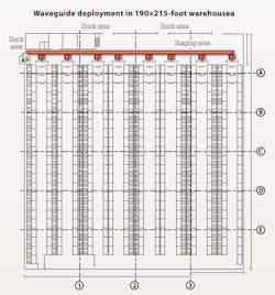
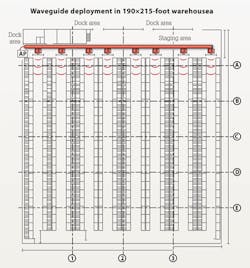
The waveguide, acting as a signal backbone across a warehouse, is placed under the red iron along a cross aisle at the ends of the product aisles, or in a pass-through aisle in the middle of a group of aisles. Nothing else is required in other areas.
Because the signal loss in the waveguide itself is extremely low, the system can be viewed as an almost lossless “bus” that divides the transmit power input to the waveguide to all of the antennas attached along the “bus.” Think of it as a set of wide-area wireless track lights. Variable signal couplers, adjustable over a 40-dB range, are placed in the waveguide at locations close to each aisle center. Each coupler’s output is then connected to a warehouse-aisle-optimized high-directivity antenna aimed down each aisle. The warehouse is thoroughly covered while providing a system efficiency (total power to antennas vs. waveguide input) that typically is greater than 80 percent.
Example in a commercial warehouse
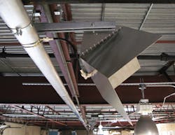
The illustration, as well as the screen capture and photos included in this article, depict an actual deployment of the waveguide system along the dock cross-aisle in a warehouse. Aisle antennas are connected to signal couplers positioned near the center of each aisle. The signal coupler, in this example, is set at 10 dB below the power inserted into the input end of the waveguide. The access point is mounted at floor level on the end of a rack. Coaxial cable is used to carry the signal from floor level to the waveguide’s input port. Although the signal loss in the 30 feet of (large size) coaxial cable is almost twice the loss of the entire run of waveguide, we have always believed that mounting APs at floor level is worth it for easy equipment access, increased equipment longevity out of the hot, dusty red iron, and is a safer place for technicians to work by not spending time on a lift.
The warehouse dimensions are 190 feet x 215 feet, with an area-under-roof of 40,600 square feet. The waveguide and aisle antennas are shown in red. Note that there are 2-, 3- and 4-pallet-deep racks, but rack depths have no effect on coverage in the warehouse.
Surveys, design and installation
Formal site surveys usually are not needed unless there are obstructions or unknown construction materials. Instead of an RF survey, a candidate warehouse should be visited to determine where the AP enclosure will be mounted—protected in black bollards, if possible—and check red-iron structure that is available to run the waveguide and mount the antennas for each aisle. A floor plan is usually available for a warehouse and is needed to start the process. Lots of pictures are useful. A good camera with a long lens helps, along with a few notes and perhaps some backup audio memos.
Design of the system is facilitated by a simulation that specifies the settings for all signal levels. And installation requires only normal hand tools, basic RF test equipment, and coaxial connector-crimp tools to fabricate the “up” cable and short coupler-to-antenna coaxial cables.
How it works
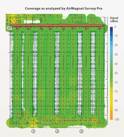
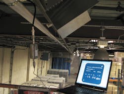
The graphic displayed earlier shows the signal levels gathered using the Fluke AirMagnet Survey Pro analyzer software, running on a Lenovo notebook computer. We recorded performance data from more than 300 points in the warehouse by walking all the aisles and cross-aisle areas that were accessible. The data was then compiled and displayed in color versus signal level.
Using the “signal thermometer” on the side of the figure, it is readily visible that the signal levels throughout the warehouse are in the low to mid -50s dBm and are consistent down every aisle. The AP used for the test was a Cisco 1240. Its specifications state that a -88dBm receive level at the AP is the threshold for 11-Mbit/sec operation, yielding an approximately 35-dB receive margin throughout all the aisles. The lower-level signals in the bottom of the figure are due to an “RF canyon” of 8-foot-high boxes electric generators that were being stored in the warehouse aisle during the tests. Even in this area, none of the signals was lower than -68 dBm, which is still a 20-dB margin in that area. And AP signal radiation outside the building is reduced.

Yes, a single access point can cover an entire warehouse at 11-Mbit/sec 802.11b. This new method of signal distribution uses a purpose-driven design to place excellent signals throughout all work spaces. It performs well with any standalone or controller-based commercial-grade access point that uses external antenna connectors. A single AP is sufficient to cover the area shown, but a total of two or three APs with adapters can be connected to a single waveguide system, if needed, to provide backup for the first AP and/or additional bandwidth. And fewer APs means fewer, or no, controller ports. ::
Charles Becker is president of Wireless Expressways Inc. (www.wirelessexpressways.com), a provider of the waveguide-style wireless systems used in the warehouse example given in this article.
Details of waveguide system deployment in warehouse
AP transmit power output: +20 dBm
AP used for test: 1 Cisco 1240
Band and speed: 2.4 GHz; 802.11b, 11 Mbits/sec
Coaxial cable loss, AP to waveguide: 1.7 dB
Total length of waveguide: 182 feet
Waveguide system construction: Passive
Output power to each antenna: +8.3 dBm
Gain of each antenna: 17 dB
Length of all aisles and racks: 175 feet
Radiation efficiency of system: >80 percent

