CFD thermal and airflow simulation improves data center design
From the August, 2012 Issue of Cabling Installation & Maintenance Magazine
Computational fluid dynamics enable economic model setup and efficient plan changes.
By Paul Rose and Andy Manning, Mentor Graphics
Data centers are expensive to build, either from a greenfield or retrofit standpoint, and operate, both from an equipment and cooling system standpoint. They must be reliable for customers to be satisfied; namely, many companies have strict criteria in terms of acceptable downtime, and so catastrophic failure of any data center component is simply not an option. Data center managers have to cope with almost anything from failure of a single CRAC unit to the total failure of incoming power or worse. Computer and communications equipment must be kept cool, under controlled humidity conditions with no rapid excursions or sustained increases in temperature.

When designing or analyzing a data center environment, we are primarily interested in temperature and airflow. We also need information about reliability and efficiency so that they can be built-in from the outset.
CFD defined
Computational fluid dynamics (CFD) is an area of fluid mechanics that uses computer-based engineering software to model and simulate the behavior of a liquid or gas within mechanical, electronic, or electrical systems. The greatest advantage of CFD modeling and simulation is that it allows design engineers and builders to examine a system design in great detail before creating a physical prototype and rapidly consider alternative designs.
CFD calculations work by first dividing up the geometrical region of interest (the volume inside or around a product), into small computational cells. Then the equations describing the fluid behavior (Navier-Stokes equations), are similarly broken down into simpler forms. This method is suited to computer-based calculations for components such as valves and vents, as well as whole designs including aircraft, cars, and buildings.
CFD is particularly useful for simulating data centers because they require operational or site testing, and scale model testing is expensive and time-consuming. CFD simulation allows you to economically set up a model and make efficient changes to the design quickly and easily. A CFD tool collects many points of data and provides advanced post-processing. It doesn’t limit you to laws of scale, and it makes it easy to set up control conditions.
Although you need to consider the entire system when analyzing issues of cooling, reliability, waste reduction, and energy use, areas such as data halls, hub rooms, communications equipment rooms (CERs), and satellite equipment rooms require individual consideration. Engineers generally know quite well how to set up these spaces using established rules of thumb, previous experience, and established design guides from required standards organizations, such as ASHRAE. Although these techniques can provide solid starting points and are suitable for simple configurations, reality interferes, and issues invariably arise with space planning, structure, site conditions, and coordination. Further, they are less applicable when fundamental design trends change; for example, the movement away from raised floor data centers to solid floor designs that incorporate in-row cooling devices.
Most problems with data halls and other front-end spaces are fundamental; for example, a unit is placed in the wrong or a suboptimal room, the room is the wrong shape, and the floor void is too shallow or is full of equipment, leading to airflow distribution difficulties.
Creating a better view
You can use CFD software to create a 3D-scale model of the data center, study the 3D airflow, heat dissipation, and temperature, test various scenarios without damaging equipment, and obtain the best balance between power requirements and equipment safety. This allows you to achieve better reliability and increased efficiency, a more consistent environment, a lower cooling requirement, and a greener, more sustainable design.
To get the most out of using CFD simulation to analyze your data center, do the following.
- Conduct first-pass modeling to get the basics right straight-away.
- Test the basic layout with your CFD tool as soon as possible while you can still inform the design.
- Quick and dirty” modeling will give you the big picture. Test this overall model.
- Don’t worry yet about the precise load distribution because it probably hasn’t been decided at this stage.
- Don’t get concerned about issues such as leakage or CRAC modulation.
- Do consider CRAC location, cabinet location, and cooling pipe routes; the effect of containment in the floor; and failure modes.
- Identify the major issues and consider the subtleties later.
A CFD tool (Mentor Graphics’ FloVENT is one example) is perfect for this first stage of modeling because it’s much easier and more rapid to use than general-purpose software. With this tool, you can very rapidly build an initial model of the room with predefined sets of units; you can assess CRAC layouts, floor void depths, and cabinet arrangements. It includes a library of tools and features such as the geometry pattern that makes it easy to assemble a model rapidly. You can also take advantage of functionality that allows the creation of common data-center elements such as CRAC, units, racks, etc., using parametric input such as flow rate and cooling capacity. Speed is the key at the concept stage while the design develops in response to multidisciplinary units.
Once you have done the roughed-out modeling in the first stage, you can refine the design with a second-pass. At this point, modeling is more sophisticated and detailed. Revisit the model, and iron out the second-order issues such as the following.
- Allowing for leakage through the floor.
- Cabinet load distribution, at least at a generic level. Many commonly available servers have Energy Star or equivalent data sheets to indicate heat dissipation.
- Structural issues; for example, columns, space cut-outs.
- Detailed containment issues.
- Identifying problem areas, hot and cold spots, and remedial measures.
- Modifying and refining floor grill layouts and opposed blade damper (OBD) settings.
- Considering effects of the CRAC controls for cooling water (CW) flow and, if installed, variable fan speeds.
- Preparing floor grill flow rate schedules for commissioning.
The tree structure in the FloVENT tool imposes order on the model, making modifications simpler and faster than most CFD codes. The decoupling of the modeler from the details of the meshing process allows individual elements of the model to be refined and modified progressively. The library allows you to move from generic cabinets to specific items of equipment as the design develops. Once a piece of equipment has been modeled, it can be repeatedly reused. At this stage, you can use the power of CFD to pick out the subtleties in the model; for example, to refine the modification of the CRAC units.
Data centers are designed with redundancy and have more CRAC units necessary to cool the IT load (often 20% more). The extra units are usually run in hot standby at full rate. More air than is strictly necessary is being moved, which takes up lot of fan power. Many modern CRAC units have VSDs (variable speed drives), so air flow can be reduced to lower power consumption. This is a particular efficiency issue where CFD can make a difference.
Designing a better banking data center
In one example, for a bank’s data center, we analyzed every feature of the design, such as the effects of room shape, floor void depth, ceiling height, equipment density, effect of containment in the floorboards, and alternative air-return methods. We started with a base case using the average flow and temperatures provided in FloVENT and then built on that, conducting 50 different simulations for the hall.
We ended up with the following typical results of varying equipment density:
- 600 mm void
- 150 mm cable depth
- Ceiling 2,900 mm above floorboards
- Cooling capacity at n+20%
The data center design uses pressurized floorboards so the floorboard depth is very important. Floor-void depth tested between 400 mm and 1,000 mm. We were able to calculate that 800 mm depth was the optimum because it was deep enough without costing as much as the 1,000-mm depth.
In this first stage of analysis, we found the optimum width for the room. With these results, the designers were able to coordinate the best way to shape the room with the electrical and structural engineers.
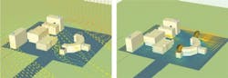
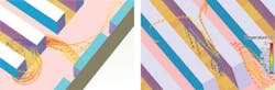
In the second pass at the model, we were able to refine the design for CRAC flows. Although the basic design of this room was reasonable, the jets from the CRAC units tended to throw air to the center of the room. This formed a high-pressure region in the center, and, as a result, air flows were much higher in the center of the room than at the ends.
The CRAC units were originally fitted with scoops that provided focused jets projecting air into the room at high-velocity. So we removed the scoops to allow the air to enter the floor void directly in the model, and the air velocity was immediately reduced. Pressures close to the CRACs increased, and pressures at the center reduced. As a result, the flow through the floor grills was more even, providing a more flexible cooling distribution.
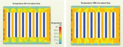
In another data center example, we constructed the model and balanced the floor grills to optimize performance for 100-percent flow. We then reduced the air flow using the VSDs to identify the lowest airflow rate that maintained adequate conditions within the space. We were able to reduce the flow to 80% and still maintain adequate conditions within the space. The temperature distribution was slightly less even because of reduction in pressure in the floor void; however, the power consumption for the room was reduced by more than 20 kW.
Using CFD analysis when designing or modifying data centers can help improve energy efficiency. With advanced thermal and airflow modeling, you can determine where and how the data center can be run a bit warmer, while maintaining reliability and efficiency. CFD simulation can then be used to determine appropriate use of cooler external air, for example, and allow you to improve chiller performance by analyzing for optimal equipment placement.
CFD analysis also can help with equipment density, allowing you to see how far you can take air-based systems and to analyze alternative cooling methods such as water and carbon-dioxide. Most importantly, a CFD tool, such as FloVENT, allows you to prototype the design early, ensure the basics are correct, and address subtle changes as the design develops. ::
Paul Rose and Andy Manning are application engineering managers with the Mechanical Analysis Division at Mentor Graphics (http://www.mentor.com).

