Specifying splices in a fiber-optic network
From the June, 2013 Issue of Cabling Installation & Maintenance Magazine
The high-strength, low-loss joints serve a network well, but only when they are properly specified and carried out.
By Eric R. Pearson, Pearson Technologies Inc.
The process of designing a fiber-optic network is not difficult. It may seem that way, due to the large number of questions that need to be answered to achieve the three goals of accurate transmission, high reliability and low cost. This article, dealing with fiber splicing, is excerpted from the manual I authored, titled "Mastering Fiber Optic Network Design – The Essentials, Version 6.0." Specifically, chapter 9 of the manual addresses specifying splices. The entire manual, including the chapter on splicing, simplifies the design process by presenting the steps in a logical sequence, identifying those questions (i.e. specifications) that need to be answered; providing options; and providing typical answers (values).
Splices are permanent joints between two fibers. They are the preferred method of connection whenever the fibers need not be disconnected or the signal rerouted at the location of the connection.
A splice provides two functions: 1) low loss, 2) high strength. Designers specify splicing in two locations: midspan and pigtail. Designers specify midspan splices when any of the following conditions exist.
- The cable cannot be obtained in a single length.
- The cable cannot be installed in a single length.
- The cable has experienced back hoe fade, post-hole driller fade, shark fade or any other form of failure.
Pigtails are short lengths of cables or tight buffer tubes with a connector installed on one end. Designers specify pigtail splicing in order to reduce installation cost or installation time. Designers specify installation of a majority of singlemode connectors by pigtail splicing.
The splicing process itself involves the following nine steps.
- Prepare the cable ends.
- Prepare the two fiber ends.
- Clean the fibers.
- Cleave the fiber ends.
- Make the splice.
- Route fibers in tray.
- Place splice in tray.
- Place tray in enclosure.
- Close and seal enclosure.
Cleaving is the creation of nearly perfectly perpendicular and smooth fiber ends. The cleave is accomplished using a toolkit; a base kit costs approximately $2,000 to $2,500; a high-precision cleaver is the single costliest item in the kit, typically costing between $1,300 and $1,600. Almost the same toolkit is used whether the installer is conducting a fusion splice or a mechanical splice.
Fusion splicng
The designer chooses between fusion and mechanical splicing. In both types, two prepared fiber ends are aligned to provide low power-loss. Each type has unique characteristics, requirements and advantages.
The installer requires the same basic toolkit for both fusion and mechanical splicing--cable-end preparation tools and a precision cleaver. Both methods require cleaving of the fiber ends to produce flat and perpendicular endfaces. Fusion splicing requires one additional tool--the fusion splicer.
The basic kit costs approximately $2,000 with a precision cleaver. With a low-cost cleaver, the kit costs less than $1,000.
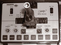
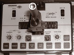
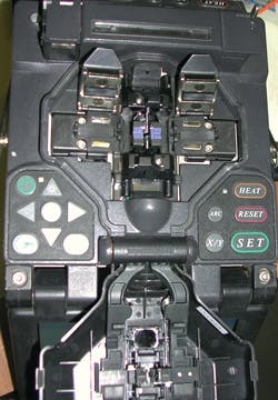
Fusion splicing is the process of fusing, or welding together, two fibers. Fusion splicing is used in most initial installations and in restoration. The process requires a fusion splicer. The fusion splicer provides two functions: 1) precise alignment of the fibers to each other prior to splicing; 2) control of the splicing operation.
The fusion splicer provides precise fiber alignment through the use of passive alignment and active alignment. It provides passive alignment through the use of a precision "V" groove. With such a groove, the splicer is based on the implicit assumptions that the fiber diameter, and the core/cladding concentricity are precise enough to achieve low power loss. These assumptions are valid for both the fiber made in North America and much of the fiber made overseas.
The splicer can provide active alignment in two ways--profile alignment (PAL) and local injection and detection (LID). In order to provide profile alignment, the splicer incorporates a collimated light source, a microscope, image digitization and analysis software.
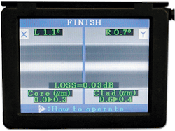
The collimated light allows the core/cladding boundary to be visible under a microscope. The digitized images are analyzed by software to define this boundary in two axes. Control software adjusts one fiber so that the offset in both axes is minimized. After the splice has been made, this same software analyzes the image to provide a value of the splice loss. This value is an estimate. The installer can measure accurate splice loss only with an OTDR. In addition, accurate splice loss is an average of the loss in both directions.
In order to provide alignment by the LID method, the splicer includes a laser light source and a detector. Both source and detector are incorporated into structures that bend the fibers. The bend at the source launches light into the fiber; the bend at the detector taps light from the second fiber. Control software adjusts one fiber so that the power at the detector is maximized.
After the splicer aligns the fibers, it controls the arc current, arc time and overrun. These parameters determine the power loss and strength of the splice.
The splice current and time control the energy provided to the fibers. The overrun provides control of the splice diameter.
Installers use fusion splicing in most initial installations and in restoration. However, installers use mechanical splicing--a process that I will describe shortly--for rapid restoration. The three advantages of fusion splicing are: 1) low power loss; 2) low to no reflectance; 3) low cost per splice.
Often fusion splicing results in 0-dB loss. Because of this low loss, some applications, such as analog cable television, require fusion splicing exclusively for permanent splicing. A low cost-per-splice exists because the only unique consumable in a fusion splice is the splice cover, with a cost of 50 cents or 1 dollar.
The three disadvantages of fusion splicing are: 1) the need for a fusion splicer, with a cost range of $5,000 to $30,000; 2) potential disruption of the profile of a multimode fiber; 3) inability to perform splicing in explosive environments.
For a small number of splices, fusion slicing may be cost-prohibitive with either a purchased or rented splicer.
The disruption of the multimode core profile is a theoretical possibility. Some research demonstrated this disruption. In 2001, FOTEC and Pearson Technologies performed such testing with a prototype FOTEC multimode bandwidth tester. This testing demonstrated a reduction in bandwidth through midspan fusion splices. The reduction was approximately 30 percent on multimode links of 200 to 220 meters. The same links exhibited high bandwidth when the midspan location contained mechanical splices and connectors. This testing suggested the possibility of failure of gigabit links with midspan splices when the links were near the maximum distance of the 802.3ae standard. This problem does not appear to occur in current-generation fibers.
The electrical arc of the splicer can ignite explosive gases. For example, methane is known to collect in manholes.
Mechanical splicing
Mechanical splicing is the process of inserting two prepared fiber ends into a mechanical splice. The mechanical splice provides precise alignment of both fiber ends and serves as a cover.
Different methods create precise alignment. Some splices have a precision capillary tube for alignment. Other splices use a precision etched silicon substrate. And one particular brand--the 3M Fibrlok--has a precision "V" groove. All mechanical splices have index matching gel at their centers. This gel fills any air gap that may result from the endfaces of the fibers being less-than-perfectly perpendicular. Such filling reduces loss. In some singlemode fibers, the index matching gel eliminates all reflectance.
Mechanical splicing is used in the following situations.
- Large number of splice teams (low-tool-cost advantage)
- Small number of splices
- Old multimode fibers
- Fast restoration
The primary advantage of mechanical splicing is that it provides fast restoration. In a fast restoration, both ends of a length of cable are prepared and inserted into mechanical splices. The splices are installed into an enclosure. This cable, stored in a carrying case, is now a fast restoration kit.
When a cable is broken, the installer brings the kit to the broken cable location, prepares the two ends of the broken cable, and inserts these ends into the fast restoration cable. Through this advance preparation, the installer reduces restoration time by approximately 50 percent.
A second advantage of mechanical splicing is low tool cost; the installer requires no fusion splicer. Purchase or rental of a fusion splicer can increase the total installed cost of fusion splicing above that of mechanical splicing.
A third advantage applies to multimode fibers; without melting the fibers, the mechanical splice cannot disrupt the core profile, resulting in no reduced bit rate.
There is one major disadvantage and one minor disadvantage of mechanical splicing. The major disadvantage is cost in large installations. At a price of $8 to $15, a 1,000-splice installation will consume $8,000 to $15,000. At $10,000, a fusion splicer is a justifiable investment.
The minor disadvantage is increased installation time. The fibers may need to be tuned to achieve low loss. Tuning is the process of rotating one or both fibers to obtain low loss. Multimode splices rarely require tuning, but some singlemode mechanical splices require tuning of every splice.
All mechanical splices grip by compression on the fiber. Some grip with a drill-chuck-type mechanism. Some grip by closing a spring-loaded mechanism.
Components of a splice
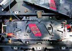
A fiber splice consists of primary and secondary components. The three primary components are: the splice, the splice tray, and the splice enclosure. The splice is the junction between two fibers. The tray protects the splice and houses excess fiber. The enclosure houses the trays and excess buffer tube.
The secondary components include gaskets, internal or integral patch panels, strength-member-gripping mechanisms, moisture seals, splice covers, grounding strips, pressure valves, locking mechanisms and plugs.
Splice cover--The installer places a splice cover over each fusion splice. This cover isolates the splice from the environment, and supports and protects the splice. Splice covers can be heat-shrinkable or adhesive. The installer places the heat-shrinkable cover on the fiber prior to splicing. In contrast, the installer places the adhesive splice cover on the fiber after splicing (or after realizing he/she forgot to place the heat-shrinkable cover on the fiber prior to splicing!).
The shrinkable splice cover consists of two layers of plastic separated by a steel rod. The rod prevents the fiber from bending when the cover shrinks.
Tray--The splice tray houses and protects the splice and excess fiber. Excess fiber allows making the splice outside of the tray. Outdoor splices require a typical length of 3 to 4 feet of fiber for each end of each splice. In contrast, indoor splices may require only 1 to 2 feet of fiber for each end of the splice.
Trays tend to be of two sizes, half-length and full-length. Full-length trays are used in outdoor enclosures; half-length trays are used in indoor enclosures or in fiber-to-the-home enclosures. Trays are designed for the number and type of splice. Trays hold 12 to 36 fibers. Additionally, trays include a splice holder. The splice holder can be integral or an insert. The splice holder is compatible with the splice cover or the mechanical splice.
Enclosure--The enclosure houses and protects the splice tray(s) and excess buffer tube length. An indoor enclosure can include an internal patch panel, complete with barrels. Excess buffer tube allows the splice tray to be outside of the splice enclosure while the installer makes the splice. Outdoor splice enclosures require a typical length of four to five feet of buffer tube per cable per end.
Comparing indoor and outdoor enclosures, some functions are similar across both types and some functions differ. Similar functions include mechanisms to grip the cable strength members, so the cable cannot be pulled from the enclosure. Not all indoor enclosures provide space for splice trays.
Other enclosure functions include isolation of the interior from environmental conditions such as moisture and dust. Some outdoor, aerial enclosures do not provide complete moisture isolation. Instead, they provide weep holes so that condensed moisture can drain from the enclosure. Unlike outdoor enclosures, indoor enclosures rarely provide such isolation.
Some outdoor enclosures installed below ground level provide positive internal air pressure to prevent moisture entrance. Such enclosures have gaskets to prevent moisture ingress or internal pressure release.
Unlike most outdoor enclosures, indoor enclosures include an internal patch panel for direct connection of connectors to the fibers in the enclosure.
Specifying the splice
The designer specifies the following characteristics of a splice: cladding diameter; splice type; maximum splice loss, in dB; enclosure size; type of enclosure; type of cover.
Cladding diameter is always 125µ. Splice loss of matched fibers for both fusion and mechanical splices is less than 0.15 dB, though some organizations allow higher or require lower values. Both fusion and mechanical splices achieve this value, although fusion splices tend to have loss lower than that of mechanical splices.
The Fiber Optic Association advanced certification process requires all splices to be less than 0.15 dB. The TIA-568-C standard allows splices to be up to 0.3 dB. Some organizations allow splices to be as high as 0.5 dB, probably for cost reasons. Finally, some organizations such as cable TV providers require maximum values as low as 0.08 dB, in order to achieve the maximum signal to noise ratio, which is an important characteristic in analog transmission systems. ::
Eric R. Pearson is principal of Pearson Technologies Inc. (www.ptnowire.com). This article includes excerpts from Chapter 9 of Pearson's book titled "Mastering Fiber Optic Network Design – The Essentials, Version 6.0." It also includes information from the book's foreword. The book can be ordered from the Pearson Technologies website.
View Archived CIM Issues
