The hidden costs of low-quality splitters

From the June, 2013 Issue of Cabling Installation & Maintenance Magazine
The heart of a passive optical LAN, the optical splitter can tempt a procurement officer to gain short-term cost savings, but doing so puts the POL at long-term risk of system failure.
By Ray Barnes and Dave Eckell, Corning Cable Systems
During the past four years, enterprise networks have seen increased interest surrounding the passive optical LAN (POL). It all started in the early 2000s, when carriers deployed fiber to the home (FTTH) as a low-cost migration path to higher bandwidth in an easily maintained network. This value has translated seamlessly to the enterprise local area network (LAN) environment. For example, in new construction or with a significant cable and electronics upgrade, a LAN operator may see up to 50 percent savings by installing a POL solution instead of a traditional LAN solution. This would include the total installed cost of electronics and structured cabling. In addition, the reduction in power consumption is attractive to businesses and government agencies trying to meet local and state power initiatives. The reality of a lower-cost alternative that meets the bandwidth needs of today's LAN environment is what is driving this interest.
However, one key aspect of the network infrastructure cannot be overlooked, as it is crucial to the long-term viability of an installed solution. The FTTH legacy brought with it a high degree of component reliability. These carrier networks were designed to last a long time and needed high-quality components with low failure rates. This forced the carriers to work with a few suppliers with the scale and quality necessary to deliver such a solution. With this increase in awareness and the adoption of POL within the enterprise market, there has also been an increase in the number of POL product vendors offering low-quality optical splitters. Of course, this is not new to the enterprise market, which has often seen low-quality products in the form of cabling and connectivity products. Network issues and failures increase the total cost of owning a network and must be taken into consideration when designing and installing a network using low-quality components. The use of low-quality splitters is particularly worrisome from a network reliability and longevity perspective. These low-quality splitters are often sold as an un-branded product at a fraction of the cost of a Tier 1 reputable optical splitter. They are often sold online and with little information as to the origin or qualification testing of the product.
For the POL, the optical splitter is essentially the heart of the network. The splitter allows a single POL port on the optical line terminal (OLT) to serve many optical network terminals (ONT) and an even greater number of users that will be connected through each ONT. This is the real value of an enterprise POL, and this value is only realized if the optical splitter is reliable, tested and designed to perform without degradation or failure for the life of the enterprise POL installation. Because the long-term performance and reliability of the optical splitter is critical to the value proposition for enterprise POL and to the adoption of this exciting technology, it is also critical that we explore the topic of the low-quality splitter.
Passive optical splitter construction
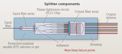
To understand the risks that low-quality splitters present in the POL, we must understand how the splitters are constructed. The splitters are actually a complex assembly made up of several components. The main components are shown in the figure on the previous page.
As shown, the passive splitter is made up of an input fiber stub, which in most cases is factory preterminated to facilitate easy coupling of the splitter into the building backbone or riser cabling. That fiber is affixed in an input fiber array that is attached to the planar lightwave circuit (PLC) chip via adhesives. Once the field fibers are affixed in the multi-fiber output array, the output array is attached to the PLC chip via adhesives. As is the case with the input fiber stub, the output fiber stub is generally preterminated to provide easy coupling into the horizontal cabling.
Splitter assembly pitfalls
During the assembly of the optical splitter, there are several potential pitfalls that can compromise the performance and reliability of the optical splitter. If one were to look at all the components of the optical splitter, they might point to the PLC chip as the most critical component, since this is essentially the heart of the assembly and the component that splits the single light input into multiple outputs. While a high-quality, high-precision PLC chip is critical to the quality, performance and reliability of the splitter, there are several other areas that cannot be overlooked during splitter assembly. First of all, contamination during the assembly process can be one of the most difficult pitfalls to protect against. In addition to causing poor performance due to increased attenuation, as can be seen with optical connectors, contamination can also compromise the adhesive bond at any of the four component junctions. This could lead to failure of the splitter assembly, which would lead to network downtime, troubleshooting and repair. Reputable splitter manufacturers take care to prevent contamination through highly automated processes that are carried out in a cleanroom environment.
Another potential pitfall of splitter assembly is imprecise alignment methods. One can imagine how difficult it is to manually align a single 9 µm singlemode fiber core with a single input trace on the PLC chip; now, imagine that you have to align 16 or 32 cores in an array, as is common in the case of 1x16 or 1x32 passive splitters. Also, imagine that once aligned, you essentially have to glue the arrays to the PLC chip. It is not hard to see where problems can arise, such as excess gap bridged by adhesive. Excess gap can lead to a poor bond between the array and the PLC chip and can lead to failure of the splitter. The problem of excess gap is usually seen in manual alignment processes that use relatively low-technology, inexpensive equipment and high amounts of inexpensive labor. This manual alignment process is used with many of the low-quality passive optical splitters on the market today. Reputable splitter manufacturers use more capital-intensive, low-labor, high-precision and repeatable automated equipment to ensure that alignment of the fiber cores to the PLC chip provides low attenuation, is reliable and is guaranteed for the life of the network, which could be as long as 25 years.
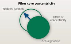
A pitfall that is common with low-quality splitters is improper fiber preparation and fiber array structure. As with installation of fiber-optic connectors, fiber preparation is a key step in ensuring high-performance, reliable connections. Proper fiber coating removal and cleaving of the bare glass fibers are essential to guarding against fiber breaks and improper alignment with the PLC chip. Fiber core concentricity is an important factor in fiber alignment. Fiber core concentricity is essentially the deviation of actual core position in an optical fiber from the nominal core position, which is essentially the center of the optical fiber.
Because the fiber array is essentially a manual V-groove alignment device, the quality and precision of the fiber array will have a direct impact on the performance and reliability of the optical splitter. Reputable splitter manufacturers will ensure proper preparation and cleaving of bare glass fibers during splitter assembly and that the fiber array is precise and durable. These safeguards can guarantee proper fiber core alignment, performance and reliability.
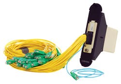
Up until now we have been examining the inner components of the optical splitter module. One version of the product most people consider an optical splitter is shown on this page.
One component that has a great deal of influence on splitter performance is the optical connections that are used to interface the splitter device in the network. As with any optical connections in the LAN, insertion loss and reliability are also very important for the connections on the optical splitter. Perhaps even more so, since the failure of a single connector on the input of a splitter would result in the loss of connectivity for all users connected through that splitter. In the case of a 1x32 splitter serving 4-port ONTs, this could be as many as 128 users. Reputable splitter manufacturers will use industry-standard connectors qualified to Telcordia GR-326 and applicable IEC and TIA standards to ensure that their connectors perform for decades and through hundreds of matings.
Testing for reliability
In order to understand the reliability of low-quality splitters in comparison to splitters from Tier 1 reputable splitter manufacturers, four low-quality splitters and two Tier 1 optical splitters were subjected to a test battery. The test was designed to predict long-term reliability by accelerating the mechanisms of failure in optical splitters. The first test was a high-temperature and high-humidity industry-standard test designed to accelerate adhesive breakdown and failure, as well as glass damage and resulting breaks. This test exposed the splitters to 85 deg. C and 85 percent relative humidity for 1000 hours. It is widely used because it is well developed and understood in the optical fiber industry and allows for reliable prediction of component failure by extrapolation to standard operating conditions.
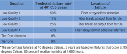
The second test that Tier 1 splitter manufacturers use to confirm the long-term reliability of their splitters is a temperature cycling test that takes the component under test (in this case the optical splitter) from -40 to +85 degrees Celsius. This test is designed to accelerate fiber failures due to glass damage. Both of the above tests were used to develop a predictive model on four low-quality splitter suppliers and two Tier 1 splitter suppliers. The table shows the results of the predictive modeling.
It should be noted that the modeling predicted that Tier 1 supplier splitters would operate at 40 degrees Celsius for 40 years without failure based on 10,000 hours at 85 degrees Celsius and 85-percent relative humidity without failure.
Cost of failure
As an individual line item, a low- quality splitter will look attractive to a procurement officer or even a project manager looking to control costs. However, the splitter cost is between 3 to 5 percent of the total installed cost of the network. This means in order to save 1 to 2 percent of the total cost of the project, the long-term reliability of the network is placed at risk.
Our testing has shown that optical splitters are more sensitive to failures than typical LAN optical components like connectors and optical cabling. This is due to the internal complexity of the assembly and the potential points of failure that result if quality, performance and reliability do not come first during the assembly process. In addition, there is great variation between branded and low-quality splitters in the marketplace.
When it comes to deploying optical splitters in the LAN, emphasis must be placed on performance, warranty and reliability in deciding which product to choose. The initial savings will be minor when one considers the downtime, troubleshooting and repair costs associated with recovering from a failed optical splitter. ::
Ray Barnes and Dave Eckell are enterprise passive optical LAN (POL) solutions managers with Corning Cable Systems (www.corning.com/cablesystems).
New TIA office includes passive optical LAN infrastructure
The Telecommunications Industry Assocition (TIA; www.tiaonline.org) took occupation of new office space at 1320 North Courthouse Road in Arlington, VA earlier this year. In doing so, the association joined the list of user organizations making use of a passive optical LAN cabling architecture and system.
The TIA accepted donations of technologies and systems from member companies for use in its new office space. Among those donating was Tellabs (www.tellabs.com), which, according to a TIA announcement, "contributed an all-fiber LAN. The Tellabs Optical LAN solution delivers Gigabit data speeds to every desktop, along with the wireless nodes, over a passive fiber network."
Also built into the TIA office is TE Connectivity's (www.te.com)Passive Optical Network (PON) infrastructure, which the association says, "will help TIA leverage the distance and bandwidth capabilities of singlemode fiber to deliver converged voice, video, data and building automation."
As TIA also explained, "The new office was expressly built to be a high-tech center of information sharing and collaboration for the information and communications technology [ICT] industry. It features the latest communications technology created by TIA members, innovative 'green' features, opportunities for companies to showcase their products and services, and significant meeting space so members can gather to collaborate on standards development, public policy and more."
The association's president, Grant Seiffert, said, "Our intent is to have an office that fosters collaboration and helps move the industry forward. With the rapid growth of mobile, the advancement of cloud computing and the advent of machine-to-machine communications, this is a critically important time for our industry. For this reason, we felt it was essential to offer ICT companies a highly functional, high-tech workplace at the federal government's doorstep. From flexible meeting space to a modern video studio, the office provides numerous opportunities for companies to work together, to stay on top of industry trends, and to showcase and present."
Other cabling and wireless technologies also were donated to TIA for its new space. Leviton (www.levitonnetworksolutions) structured cabling products as well as CommScope (www.commscope.com) in-building distributed antenna system technology are used at the new TIA facility.
TIA' optical sps move to and buildout of the space was a STEP pilot project. TIA is a founding member of the STEP Foundation. -Ed.
View Archived CIM Issues

