Laying the groundwork for high-performance wireless access
From the January, 2014 Issue of Cabling Installation & Maintenance Magazine
Enterprise IT managers must consider new strategies for integrating wireless capabilities into the core network, and for the cabling backhaul to support them.
By Masood Shariff, CommScope
Until recently WiFi within the enterprise facility was considered a supplementary leading-edge service--offered to visitors and occasionally used by staff. That is no longer the case; from office buildings and airports to shopping malls and sports arenas, wireless access is a basic expectation. Employees, customers and tenants assume they will be able to access the data and services they want, regardless of where they are or what type of mobile device they are using. The increasing dependence on wireless communications is illustrated by the rapid adoption of bring-your-own-device (BYOD) policies within the enterprise. At many sites, the increasing demand has also opened up a significant gap in service performance, as devices and applications apply larger amounts of data and rely on faster response and throughput.
Faced with accelerating trends like BYOD, enterprise IT managers must consider new strategies for integrating wireless capabilities into the core network. This involves rethinking how wireless access points (APs) and infrastructure cabling are deployed throughout the facility, and how this influences traditional cabling infrastructure. While direct access to data cabling will always provide bandwidth capabilities beyond those of a shared and open wireless network, significant advances in wireless speed, capacity and performance have created new issues and opportunities in terms of network design.
As a result, today's enterprise IT personnel face difficult and complex challenges. As efficient and fast as today's wireless access technologies are, they all require the support of a wired data network whose cabling infrastructure is up to the task. If not implemented correctly, the traffic demand for wireless or WiFi service can easily outstrip the capabilities of the network's cabling infrastructure. At the same time, new and existing wireless standards make for additional complexity that enterprise IT managers must face.
This article, derived from a CommScope white paper, was written to provide guidance and recommendations for enterprise IT professionals who are charged with designing and deploying the cabling infrastructure to support their rapidly expanding needs for wireless access.
Opportunities and challenges
The WiFi Alliance defines WiFi as any "wireless local area network (WLAN) products that are based on the Institute of Electrical and Electronics Engineers' (IEEE) 802.11 standards." (Source: Webopedia.com, "What is WiFi?") Currently there are two prevailing 802.11 standards of interest: the older 802.11n and the newly released 802.11ac.
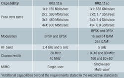
IEEE 802.11n: Ratified by the standards committee in 2007 and introduced to the market in 2009, IEEE 802.11n uses 20-MHz or 40-MHz channels in the 2.4-GHz or 5-GHz spectrum and supports speeds up to 600 Mbits/sec. It was the first WLAN standard to incorporate multiple input/multiple output (MIMO) technology, which enables the transmission of multiple radio signals on different antennas in order to mitigate radio frequency (RF) impairments and enhance transmission rate and reliability.
802.11n is now widely deployed in the enterprise space and has provided the primary support for wireless growth in commercial buildings. A typical installation uses dedicated cabling channels to wireless access points for carrying traffic back to the facility's overall network. Equipment compatible with 802.11n is also backward-compatible with older 802.11b/a/g standards, with various generations of equipment typically coexisting in a given network.
Despite its advantages, IEEE 802.11n presents limitations for WLANs when it comes to satisfying the growing need for improved wireless performance. Shortly after introducing the 802.11n standard, the IEEE wireless standards committee began work on a new standard that would allow for higher performance.
IEEE 802.11ac: In June 2013 the IEEE ratified the standard for 802.11ac, the newest generation of WiFi technology. IEEE 802.11ac supports increased performance and capacity that will eventually support aggregate data rates up to 6.9 Gbits/sec--more than 10 times faster than the top aggregate speed of 802.11n. The enhanced technology uses frequencies in the 5-GHz band and more-sophisticated modulation techniques to provide access to many more non-interfering independent channels. The additional range of interference-free channels creates greater flexibility and a more-complete WLAN solution capable of meeting the growing demand for increased wireless performance.
Rollout of the new technology has been aggressive. As of June 19, 2013--the same day the completion of the standard was announced--the WiFi Alliance approved 19 routers, access points, microchips and smartphones as 802.11ac compatible. "Usually, our certification programs serve as one of the contributing factors to widespread market adoption, but already this feels like a much more accelerated adoption than in years past," Kelly Davis-Felner, WiFi Alliance director of program management told CNN Money.
Implications for backhaul cabling
According to an Information Week 2013 WLAN survey, more than 45 percent of IT executives have plans to deploy 802.11ac gear on their production networks; more than half of those are planning to move as soon as product is available. A recent ABI Research forecast predicted that 40 percent of smartphones would support the newer version of WiFi by the end of 2013. Furthermore, the WiFi Alliance expects that 802.11ac devices will make up the majority of the WiFi market this year.
The enthusiastic adoption of 802.11ac, along with its fast data rates and wider channel flexibility, present serious problems for backhaul networks designed to support current 802.11n deployment. In its lowest configuration, 1x1 MIMO, 802.11ac support 866 Mbits/sec--44 percent faster than the fastest 802.11n. But when configured for 8x8 MIMO, the technology tops out at over 6.9 Gbits/sec. 802.11ac also supports advanced antenna capabilities, including beamforming, that allow wireless users to reliably access gigabit speeds simultaneously. The new channel availability also now supports high-density AP deployment for configuring WiFi service with advanced capabilities.
Operating at capacity, 802.11ac equipment is capable of far exceeding the performance provided by 1000Base-T uplinks. Even 802.11ac-certified devices operating at the lower end of the speed spectrum may come outfitted with two 1000Base-t uplink ports and link aggregation support. Future offerings can be expected to use 10GBase-T, or possible dual or even quad 1000Base-T uplinks, to support the multi-gigabit backhaul.
For the enterprise IT manager, the new level of density and speed and the required backhaul capacity of IEEE 802.11ac are game changers. To manage this change, IT professionals must pay extra attention to how and where their AP network is deployed, as well as the cabling infrastructure needed to carry the backhaul traffic, now and in the future.
IEEE 802.11ac is poised to be the first application to exceed the performance of the widely deployed Category 6 cabling, and it will not be the last. Considering the rapidity with which new wireless technologies are being introduced, today's physical cabling infrastructure must be designed with enough capacity and flexibility to support the enterprise over the long term.
Standards for cabling wireless access points
The ongoing developments in wireless technology have prompted industry organizations to revisit and, in some cases, revise the existing standards addressing the layout, cabling and connectivity of today's advanced wireless networks. A brief look at a few of these standards shows the work that has been done and helps place the IT manager's challenges in context.
Many of the standards addressing wireless networks focus on premises cabling for access points and strategies for connecting to the facility network. The challenge, however, is in the design. Specifically, how can IT managers use optimally sized cells to create a WLAN capable of delivering both IEEE 802.11n and IEEE 802.11ac applications while supporting it with a backhaul network that can handle current and future capacity?
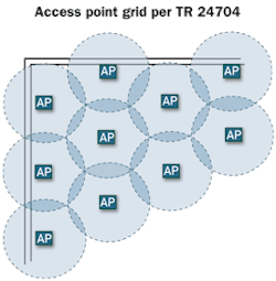
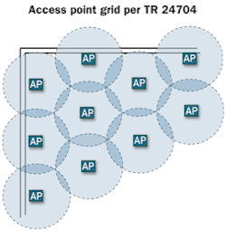
In 2004, the International Organization for Standardization (ISO) and International Electrotechnical Commission (IEC) introduced technical report TR-24704, focusing on "generic cabling for customer premises, for connection to wireless access points." (Source: ISO/IEC technical report "Information technology--Customer premises cabling for wireless access points") Drafted during the formative years of enterprise WiFi, the technical report contains remarkable vision in anticipating the advanced capabilities of today's wireless equipment and technologies.
In establishing standards for wireless access cabling, TR-24704 proposed what it considered to be an optimal pattern for locating wireless access points. The design is based on an array of tight-fitting hexagonal cells. Using omnidirectional antennae, the radiation pattern within each cell is a circular pattern. When properly arranged, the combined average areas provide a minimal but optimum overlap.
To accommodate higher capacity, the coverage area of each cell is limited to a 12-meter radius. TR-24704 recommends terminating the cable for each cell at an outlet located as close to the center of the cell as possible. This provides maximum flexibility and coverage in optimizing the locations of individual access points.
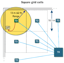
Soon after the release of TR-24704, the Telecommunications Industry Association (TIA) introduced its own cabling guidelines for wireless access points. Currently in revision, TIA TSB-162-A suggests a square grid of cabling areas, each 18 meters wide. This approach more closely corresponds to typical building bay layouts used in North America, simplifying design and installation. The placement of the access points assumes a radius--and drop-cable length--of 13 meters. In anticipation of the IEEE 802.11ac evolution, the revision of this standard recommends Category 6A cabling to provide sufficient bandwidth and increased current-carrying Power over Ethernet (PoE) capacity.
Toward the end of 2012, TIA introduced another standard in order to address appropriate access point density. TIA-4966 is specifically designed to cover educational facilities, but the recommendations are useful for any large indoor areas or buildings with high concentrations of wireless clients. These guidelines identify variations in wireless coverage based on their usage.
TIA-4966 recommends that access point density within large open indoor spaces be based on expected occupancy. When developing a coverage plan for facilities with multiple partitioned areas, density should be based on square footage. A "typical" office building would suggest one access point per 230 square meters. Facilities that may be less RF friendly--residence halls, for example--suggest one per every 150 square meters.
Planning for the wireless access networks
Despite the variances in the standards, each provides information that can aid the IT manager in designing an efficient and high-capacity WLAN. Of course, designing an advanced wireless access network requires an understanding of the process that goes well beyond standards-based suggestions.

Taking full advantage of the benefits of technologies such as 802.11ac involves careful planning with regards to the facility's RF environment, interference levels and sources, future capacity needs, cabling requirements and power needs. The remainder of this article provides an overview of these variables and some of the strategies being used during the planning phase of a WLAN project. This is not meant to be an exhaustive analysis of the current methodologies, but more to give the IT manager guidance regarding the cabling infrastructure considerations and a general idea of the level of planning needed to implement a successful access point network deployment.
Ideally, the cabling architecture and coverage analysis should work hand-in-hand to provide the maximum capacity and flexibility to meet both current and future end-user needs. In practice, there are distinct advantages in the grid approach specified in TIA TSB-162-A and ISO/IEC TR 24704, especially for new buildings.
In a new building, the pre-cabled access point coverage grid and the structured cabling for IT and facilities operation can be designed and installed at the same time and by the same teams. Once the pre-cabled grid is in place, the facility's wireless infrastructure can be installed at any time with minimal disruption. When locating the access points, it is recommended that an RF survey be conducted to optimize the access point location(s) within a given cell.
The above figure represents the floor plan of a small, one-floor office with slightly more than 2,000 square meters of interior space. It features about 23 offices, 900 square meters of lab space, client meeting rooms and various common areas. Parking areas run along two sides of the building and the office shares an adjoining wall with the business next door.
RF environment
Most WLAN vendors will recommend that new installations go through an analysis of the RF environment as part of the overall site plan and wireless solution. In environments in which capacity and other concerns are minimal, simply assessing RF propagation may be sufficient. In other cases, it may require a more-thorough analysis including interference, throughput and security issues. The newer 802.11ac standard allows for significantly more network equipment and traffic, making a thorough site analysis even more important. The goal is to ensure that the site can fully support the present and anticipated mobile connectivity demands.
Using a site-mapping tool, such as the Fluke Networks AirMagnet WiFi Analyzer, the wireless performance characteristics of the facility can be mapped, studied and optimized. The program allows network planners to input the site's layout, conduct access point modeling and compare RF simulations and surveys. It also provides report generation and can be integrated with WLAN management solutions, making it an ideal starting point for wireless design.
The figure immediately below shows the RF power levels from a single deployed access point, as assessed by the AirMagnet WiFi Analyzer. This most basic arrangement is typical of existing sites that only need occasional wireless access for visitors. Although common today, this simple implementation is quickly becoming outdated with the increasing demand for more wireless speed and capacity.
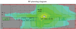
The color changes on the map denote differences in signal strength, with gray showing the weak RF signal areas. The eastern end of this site receives a strong RF signal from the access point. While the signal on the west end is mostly weak, it could still be operational provided there is minimal interference. Signal weakness could be due to a number of variables, including the presence of RF-blocking materials such as cabinets or equipment, or structural impediments such as concrete walls or steel bulkheads. This accounts for the abrupt drop in signal strength on the side of the model shop opposite the access point.
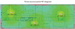
The bottom figure illustrates how adding two additional access points significantly improves coverage. Virtually all of the weak areas previously exhibited have been eliminated. Such an arrangement is typical of 802.11n solutions in which the access points are each set to use non-interfering channels. While this configuration provides adequate RF coverage, it is somewhat limited in its ability to support extensive use of WiFi. Along with ensuring adequate RF signal, the aggregate throughput that will be needed should be considered.
While the configuration shown could easily support a handful of light clients within range of each access point, heavy use can easily overwhelm the nearest access point. Thirty or more clients expecting broadband access in a meeting, for example, would generally be disappointed with throughput and may experience connection-reliability issues. So while this typical arrangement satisfies a minimal level of business WiFi service, it falls short of the performance required by today's typical business environment.

The first step in planning for higher capacity and coverage is to divide the space into grid cells as recommended by TIA TSB-162-A or ISO/IEC TR 24704. The figure that follows shows a sample floorplan that has been divided into a grid pattern identifying 12 areas for access-point cabling support. It should be noted that this grid-type pattern can also accommodate the cabling needs for other facility networks. Deploying this integrated and more open-ended cabling strategy provides short- and long-term advantages.
The middle figure shows how the RF coverage within the grid improves when using 14 highly localized access points, each capable of supporting extensive high-capacity wireless access. Although the wireless bandwidth is still shared, more access points and channels are available for use throughout the facility.

Using the square grid layout supported by TSB-162-A, access-point positions and density can be adjusted to suit the occupancy. Meeting areas, for example, will require multiple access points while lab space can be more limited.
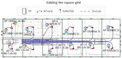
Note that, while actual access point placement should be based on current space usage, good cabling practice should plan for future changes in use. Cabling support should start with the grid planning, as shown in the structured cabling diagram, and incorporate the applicable strategies outlined in the standards to ensure that adequate cabling is in place for future needs.
The diagram illustrates one such potential cabling strategy. Aided by the site-planning tool, the design ensures adequate cabling is in place to support each grid cell. Note that most of the grid cells need only one access point, while higher-traffic areas such as the meeting room need two or more access points. Therefore, it is recommended to provide at least two cabling runs to each grid cell. It is important to note that this same grid-cabling strategy can also be used to support other facility services such as security, energy and lighting. Preplanning involving all network operations can produce significant savings during installation as well as ongoing upgrades, maintenance and repair.
Access point location and cabling
In addition to the RF environment and capacity planning, there are a number of other factors to consider in cabling and locating wireless access points. These include accessibility, distribution, power requirements and aesthetics.
Accessibility: In many cases, wireless equipment locations can be difficult and time-consuming to access. Selecting the right location can save on maintenance and upgrade costs, lowering the overall operational expense (opex). The access point location should be unobtrusive yet accessible. With common above-ceiling installations or lockable enclosures, the hardware and cabling may be installed in a plenum space. However, wall-surface or ceiling grid-mounted installation usually is preferred. This allows for quick and easy visual inspection of the access point status lights.
The same care should be taken when locating an access point telecommunications outlet (TO). Providing a service-friendly TO adjacent to each access point allows easy line testing and allows for a quick disconnect when access point equipment must be removed for service or upgrade.
Distribution: In a traditional network cabling topology, each access point's TO is directly connected with a horizontal cable to the patch panel in the telecommunications room for that floor. A zone distribution system is an alternative design that may provide easier installation, greater flexibility and potentially lower opex.
A zone distribution model uses cable runs from the equipment room to specific "building zones." A consolidation point (CP) within each zone allows fixed cabling to be installed up to the CP; drop cabling then runs from the CP to the TO for each access point. This approach provides additional flexibility in cabling from the CP to the first TO in each cell, as well as providing spare capacity for additional TOs as needed. This strategy is helpful during retrofit installations, where well-placed consolidation points allow long runs of cabling bundles from the telecommunications room to be fixed into difficult pathways. Once the fixed cabling is in place, installers have more flexibility in running and changing extension cable from the CP to the TO serving the access points and other intelligent building equipment.
Power sources: Another important consideration is the power requirements for the wireless access points. If the access points are line powered, coordination with the facility's electrical service will be needed. In a high-capacity installation using plenum space, this can be complicated. For this reason, most access points are designed to use PoE sources from the backhaul switching equipment. To ensure reliable operation, performing channel PoE verification is recommended. This is especially important for access points deployed in obscure areas or that may be subject to harsh operational conditions.
Power requirements for the newer 802.11ac-certified access points, however, present a new wrinkle. Designers should consider running at least two Category 6A cables to each access point. This strategy can provide backup or redundant communications and PoE power from two different backhaul sources, allowing the access point to continue functioning should a switch or PoE source go down.
Aesthetics: It is aesthetically preferable to keep all wireless network cabling, including TO wiring and attachment cords, out of view. Often this is accomplished by supporting and hiding them using the facility's structural components. This can sometimes be a challenge where unique architecture and/or interior design cannot be altered. The details of methods and placement should be discussed with customers regarding aesthetics and any expected impact on wireless coverage.
Selecting cabling types
From a topology perspective, access point cabling is treated as horizontal cabling--similar to the cabling from the telecommunications room to the TO in an office. Most current in-building installations use at least Category 6 balanced twisted-pair cabling. Category 6 provides the necessary backhaul capacity and can support PoE Plus, an updated IEEE 802.3at power standard for PoE applications up to 25.5W. For the newer, higher-capacity 802.11ac solutions, Category 6A cabling should be used.
Finally, most access points feature RJ-45 Ethernet ports, compatible with balanced twisted-pair cabling. However, some feature multimode optical fiber ports with LC connectors. These are typically used to support access points installed outdoors, or to support cabling distances longer than 100 meters. If fiber is used, it should be at least two pairs of Om3 or higher multimode fiber to ensure sufficient bandwidth for each access point. When deploying fiber, the power for the access points must be provided locally.
New building vs. retrofit
Obviously, installing a wireless access network in a facility under construction, before any non-load-bearing walls are in place, presents more options than retrofitting an existing space. In these locations, the focus should be on optimizing coverage and ensuring the greatest flexibility for future growth and change. For these reasons, the grid design and TO placement guidelines provided in TIA TSB-162-A and ISO/IEC TR 24704 should be followed. The design may use zone cabling or home runs to the center of each cell, keeping in mind that a zone cabling strategy provides maximum flexibility for future, cost-effective adjustments. Once the space partitions and furniture are in place, installers should conduct an RF survey to determine the optimal positioning of each access point.
Retrofit installations, on the other hand, require a careful assessment of the facility and a customized approach to support access points. When planning for a retrofit, having a solid grasp of the RF environment in existing facilities is critical, especially considering the difficulty of routing cables in existing buildings. Therefore, it is strongly recommended that IT managers perform a complete RF and anticipated throughput analysis prior to cabling and access-point installation. The design team should pay special attention to areas requiring specialized coverage or those where the need for future capacity growth may be anticipated.
Once the analysis is complete, the work of placing the access points and TOs, and developing the cabling strategy, can begin. Considerations include the following.
- Access to ceiling space for cable pathways to the TOs for each access point
- Availability and proximity of existing distribution pathways to planned access point locations
- Architectural and aesthetic considerations to hide the access points and associated cabling
- RF coverage environment
The grid layout recommended in TIA-162-A or TR 24704 is preferable but may not always be feasible, especially in retrofit environments. If the distribution pathways are full or do not support a square grid layout, additional pathways will need to be installed. In this case, the zone-based CP cabling design is recommended in order to achieve the best possible coverage and support future growth.
Recommendations
IT professionals are scrambling to keep up with the explosive growth of wireless devices and the consequential demand on wireline and wireless networks. Supporting higher-speed wireless access points is a critical aspect of managing this growth. IEEE 802.11ac has introduced gigabit access to wireless clients and multi-gigabit backhaul requirements from the access point to the access switch or controller.
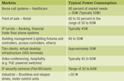
The increased capabilities of today's wireless access points also have resulted in higher power requirements. Some powering technologies available today can support up to 60 watts at the powered device. To keep pace with these developments, CommScope recommends the following.
- At least two runs of Category 6A cabling to each access point, preferably using a zone architecture.
- At least four runs of Category 6A cabling per access point to each zone distributor, to provide future additional capacity to each access point or support the installation of additional access points with minimal disruption.
- Pre-cabling using the square cell grid strategy that allows easy plug-in and flexible positioning of access points.
- Multimode fiber for backhaul should be considered when data rates higher than 10 Gbits/sec are anticipated and for outdoor locations where distances are greater than 100 meters.
- Mixed use of older and newer wireless access points should be limited to a transition phase because older versions can slow network performance.
- Site surveys and performance evaluations using functional access points and clients should supplement the pre-cabling and access point layout to optimize the placement and programming of each access point.
The final step
Since its introduction in 1997, 802.11--the original IEEE wireless access standard--has evolved exponentially. In just 16 years, peak data rates have increased from 2 Mbits/sec (with IEEE 802.11) to 6.9 Gbits/sec with IEEE 802.11ac. In all there have been five iterations to the original standard. More important, the average span between new standards is just 42 months. There is no reason to assume the trend in increasing speed and capacity will slow after the recent introduction of IEEE 802.11ac.
A critical consideration for the IT manager is not just whether the selected network components can support the immediate wireless needs of the enterprise, but whether they will be sufficient to handle the imminent upgrades in the very near future. Of the various wireless network components, cabling is often the most difficult to upgrade.
To keep from having to replace the wireless network cabling each time a new technology is adopted, it is important that the IT manager selects cabling that is supported by a long-term applications warranty, preferably 20 years. Whereas a product warranty guards against physical shortcomings of the cable, an applications warranty ensures that the cabling infrastructure will continue to perform as specified for applications developed by known standards bodies.
Masood Shariff is engineer senior principal with CommScope (www.commscope.com). This article is derived from the white paper titled "Laying the groundwork for a new level of wireless access performance," which is available at CommScope's website. That paper contains graphics and other information not included in this article.
Archived CIM Issues

