Bringing it all together, optically
From the August, 2014 Issue of Cabling Installation & Maintenance Magazine
Optical fiber connectors for present and future networks
By David D. Cook, 3M Communications Markets Division
Fiber-optic connectors play an integral role in network performance, even more so as data rates increase and system loss budgets get tighter. There is an ongoing need for connectors that provide low losses, small footprints, easier termination and lower-cost solutions, and users have a variety of options to meet their network-design needs.
The most common connectors in use today are the SC (Subscriber Connector), the ST (Straight Tip), and the FC (Fiber Connector). In addition, small-form-factor connectors such as the LC (Lucent Connector) are used in high-density optical transmission products and for applications including fiber-to-the-home and dense wavelength-division multiplexing (DWDM), where space is at a premium. Another connector gaining popularity is the MPO (Multi-Fiber Push-On), which is used for high-fiber-count terminations that use ribbon fibers.
Each design has pros and cons, so when choosing connectors, it's important to consider several factors. Important considerations include the application, the data rates that need to be supported, the training of the installers as well as fiber type because multimode and singlemode fibers require different connectors. This article will provide an overview of the various defining characteristics and features of the most common connectors to help you understand which options will best optimize the performance in your network. It will also explore the most common field termination techniques.
Connectors' role
Connectors are used to mechanically connect two optical fibers, allowing the light to transmit from the core of one fiber into the other, or to link to fiber-optic transmission equipment. To achieve this connection without incurring high light losses, the cores must be accurately aligned and the fiber endfaces must be properly prepared and clean of debris, scratches or chips.
Different connectors are used for singlemode and multimode fibers. Termination procedures may or may not vary slightly. With a larger core, multimode fibers are more easily aligned and, therefore, have more forgiving tolerances. Singlmeode connectors require tighter tolerances and their termination requires more care. Any dirt, scratches or imperfections in the singlemode endface surface will adversely impact performance more readily than with multimode connectors.
Connector anatomy
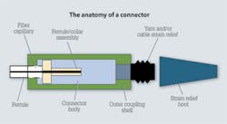
Figure 1 shows the main components of a connector. The ceramic ferrule at the front is designed to support and center the fiber, providing low-loss fiber alignment. The ferrules are held within a collar assembled inside the connector body, and there is usually a spring within that connector body that pushes the ferrules forward to make the fiber-to-fiber contact or the connection to the equipment.
The ferrule and spring are surrounded by a connector body and coupling shell that provide a robust connection to equipment and the coupling/adapter. Additionally, there is often a mechanical strain relief at the back for robust cable tensile load and twist resistance. At the end, a strain relief boot provides cable side pull bend control. The connector body materials are chosen for stable temperature performance.
It is important to read the vendor's specification sheet to match the connector performance to the intended application. Remember to take into consideration the size and type of the cable to be terminated to choose the proper part number.
Issues affecting performance
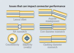
To achieve a good connection, it is important to have a very good fiber core-to-core alignment and a good fiber endface finish. A critical performance factor in a connector-to-connector interface is controlling lateral offset, or the alignment of opposing fiber cores. As you see in the upper-left corner of Figure 2, when the fibers are misaligned, a percentage of the light misses the core of the mating fiber. The light gets lost in the fiber cladding and is no longer part of the optical signal. This light loss, or attenuation, lowers your bandwidth and reduces the distance the signal can travel through the optical fiber.
Another factor that needs to be considered for connectors is angular misalignment. Connector ferrules are designed to hold fibers in a very straight position as they are inserted into the end of a connector. As two connector ferrules are brought together, a mating sleeve holds them straight, in alignment, with one another. As shown in the upper-right illustration of Figure 2, any slight angular misalignment can be compensated for with a commonly used endface polish called Physical Contact (PC). Using a PC finish improves the way the cores contact each other and reduces the chance that there will be an air gap that the light will need to pass through.
A numerical aperture mismatch can happen if you have a fiber-to-fiber interface that has distinctly different types of fibers. Core diameter mismatch, concentricity, the ellipticity, or the cladding diameter mismatch typically are not seen in the field anymore; the precision of fiber manufacturing has mostly eliminated these types of problems. With the precision fibers manufactured today, the connector design is less about fiber geometry. A greater focus is placed on holding a fiber of a consistent diameter and concentricity in the center of the ceramic ferrule.
Preparing the endface
The fiber-optic connector endface is always polished after termination to remove surface defects and to improve optical qualities. A pristine endface "window" will minimize light loss and back reflection. Some connector types require field polishing, which entails using a soft pad with a polishing grit to smooth the fiber endfaces. The technician polishes the endface in a figure-eight motion, which allows for equal polishing on all angles and edges of the fiber.
In a similar way, factory machine polishes are used in a batch process to prepare preterminated cable assemblies, like patch cords, or perhaps preterminated cables that are pulled into backbones or even in horizontal applications.
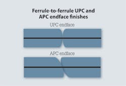
A very common endface finish is known as UPC, which stands for "Ultra Physical Contact." This very fine finish has no cracks, chips or scratches on convex endfaces and allows for a very efficient fiber-to-fiber connection. Also used is an Angled Physical Contact (APC), which includes the addition of an 8-degree angle. An APC finish provides very low signal reflection; any reflection that does occur in the APC interface is lost into the fiber cladding and does not become noise in the system. APC connectors are used where low reflections are required, typically cable TV applications and analog video systems.
The geometry of the fiber together with the geometry of the ferrule need to be tightly controlled with the polishing technique. In some applications, connectors need to perform in extreme operating conditions, such as temperatures that range from -40 degrees C (-40 degrees F) to +85 degrees C (+185 degrees F). These temperatures can cause the fibers and the ferrules to move. The materials and the polished geometry of the endface are all very important to being able to maintain a good connection through those extreme environmental conditions.
Performance requirements
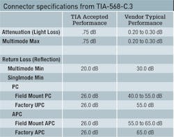
ANSI/TIA-568-C.3 defines the performance specifications for fiber connectors typically used in structured cabling systems. Attenuation or light loss is the most critical, and is usually used to measure the performance level and quality acceptance of a field-installed connector. Remember that with tighter light loss budgets on high-speed networks, you may have less headroom for additional high-loss connections. Although the standard specifies a maximum attenuation loss of 0.75 dB per mated pair of connectors, depending on your application, the amount of loss per connector pair may be significantly less.
Reflection, also known as return loss, can be an issue, particularly for singlemode systems. The standard specifies a minimum of 20 dB for multimode fiber and 26 dB for singlemode fiber. To reduce reflection, it may be necessary to use an angled polish.
For TIA 568-C, connectors must perform within a range of temperatures from -10 deg. C (14 deg. F) to +60 deg. C (+140 deg. F) and be able to withstand humidity, impact, and various stresses on the cables that might cause connectors to flex or twist. Again, consult the vendor connector specification sheet to understand the performance level that the product has been tested to withstand.
Choosing a connector
There are dozens of connectors available on the market and this article focuses on some of the most common types. Even among those detailed herein, there is a strong movement toward small form factor (SFF) connectors like the LC and multifiber connectors, such as the MPO, as networks move to support higher-speed applications including 40 and 100 Gigabit Ethernet.
ST connectors are keyed bayonet connectors that have been used for many years in local area networks, particularly in networks running 10Base-F and 100Base-F. They are not as popular today, but there are millions installed, and it's common when maintaining older networks to find them using ST-type connectors. ST connectors use a 2.5-mm ferrule. They are used for both multimode and singlemode fiber and can be inserted and removed easily in connection. They have a typical insertion loss for matched ST connectors of 0.25 dB.
SC connectors are snap-in connectors that latch and disconnect with a push/pull motion. They are used for both multimode and singlemode fiber. Their ease of use and performance have made them one of the most popular connectors. They are widely found in networks running Gigabit Ethernet. SC connectors use a 2.5-mm ferrule. Typical mated SC connectors have an insertion loss of 0.25 dB.
LC connectors are considered small form factor (SFF) connectors-just one half the size of an SC connector using a 1.25-mm ferrule. LC connectors are used with singlemode and multimode fiber-optic cables. The typical insertion loss for LC connectors is 0.25 dB.
MPO connectors are high-density, multifiber connectors that use a push-on or slide-on mechanism similar to the SC. MPO connectors are the standard physical format for high-speed networks such as 40 and 100 GbE. They can be provided in multiple versions, starting with 4, 6, 12 fiber, and then also available in 24, 48, and even up to 60 fibers in a single connector array. When these are connected, all 12 of the fibers need to align center to center, so this connector requires accuracy to manufacture. Alignment between mating ferrules is accomplished using two precision guide pins that are preinstalled into the male connector. MPO connectors are used with both multimode and singlemode fiber cables, and the typical insertion loss is 0.25 dB per mated fibers.
Field termination methods
Over many years of fiber-connector development, connector manufacturers have created several designs of connector termination methods. In addition to choosing a specific connector type, the type of field-termination method selected can be determined by your installer's skill set, available tools and simply personal preference. Some methods provide differences in optical performance, while other methods may provide ease of use, resulting in lower labor time.
There are four basic types of field-termination methods commonly used for connecting fiber networks: adhesive polish, fusion splice-on, mechanical splice-on, and cleave crimp. Whichever method you use, it's important to follow manufacturer-recommended procedures and use only the proper materials.
In this section, the SC style connector is used to illustrate the four termination methods.
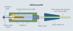
Adhesive polish-The adhesive polish termination method has been used since the 1980s, when fiber connectors were first developed. The method is still used because it can achieve low loss and high reliability at a very competitive cost. The downside of this approach is the complexity of the process and the time required to cure the adhesive, potentially resulting in longer termination times. After epoxy cure time, there is a one-, two- or even three-step process of polishing the fiber and a supporting bead of adhesive away from the endface of the ferrule. A final finish step creates the pristine fiber endface.
Benefits: Operates over a wide temperature and humidity range; provides very durable connection; low cost per connector; dependable and stable in a wider range of most environments depending on the choice of adhesive used.
Challenges: Multiple steps required to mix and apply the epoxy; may offer less than 100- percent yield; can be time-consuming; requires skilled training and supervision.
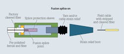
Fusion splice-on-The fusion type splice-on connector is applied in the field using a fusion-splicing machine. A connector with a factory-cleaved fiber within a prepolished ceramic ferrule is used with this method. The factory-cleaved fiber protrudes from the end of the ferrule into a splice protection sleeve. The ceramic ferrule and collar are placed into an adapter in the fusion machine. Once fused, the connector parts are then assembled around that ferrule body. The cable can then be strain-relieved, typically with a crimp to the jacket. A properly performed fusion splice can provide a very low-loss, low-reflection connection.
Benefits: The prepolished endface on the end of the ferrule is a pristine, factory finish; no polishing is done in the field; produces a low-loss, low-reflection connection.
Challenges: High equipment cost; requires power on-site or charged batteries; higher skill level and training required.
Mechanical splice-on-The mechanical splice-on method uses a preassembled connector with a mechanical splice element inside. The preinstalled fiber has a factory-produced polish on the endface of the ferrule and a factory cleave on the inside of the splice element. In the field, the fiber cable is stripped, cleaved and inserted into the connector. Once the fiber is in contact with the cleaved fiber inside the splice element, the element may be actuated, either by hand or with a tool. Typically there is a secondary buffer clamp and a method to retain jacketed cable.
Benefits: Fast and easy to install; fewer tools; little training required; good return on investment; high yields.
Challenges: Higher first cost of materials.
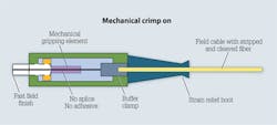
Mechanical crimp-on-A mechanical crimp-on connector contains no splice or adhesive. A mechanical crimping element grips the fiber, but there isn't any fiber interface inside the connector, as with the splice-on types. The field fiber is threaded through the ceramic ferrule after it has been cleaved and positioned with a little bit of fiber protrusion beyond the endface of the ceramic ferrule. A tool helps position the fiber properly. A small amount of fiber finishing brings the fiber endface flush with the ferrule end and creates a physical contact (PC) finish on the fiber endface. The short fiber protrusion and the lack of adhesive allows for innovative ways of finishing without having to do figure-eights or going through multiple steps of polishing. The absence of a splice eliminates a potential point of signal loss. With no adhesive, the two fibers come in direct contact between the two ceramic ferrules. The design allows the fibers to maintain good contact, even through temperature changes.
Benefits: No epoxy/adhesive to manage; termination is easy and fast; no additional loss in splice point inside the connector; good return on investment.
Challenges: Higher first cost of materials.
Tools and training
The good news about field terminating connectors is that with all of the available methods and designs, it is generally easy to get a good, low-loss connection without extensive training. A person with common dexterity can learn the techniques to install connectors in well under an hour and can assemble connectors in two or three minutes. Most manufacturers provide a template outlining lengths needed to strip, cleave and finish the end of the fiber cable with simple-to-follow instructions. Additionally, there are independent training schools that offer classes. Vendors may also provide training sessions with online videos available for reference. That said, it is important to read and follow the instruction manual and use only the materials specified. There are differences among the vendors and it's important to use the techniques outlined to ensure a good connection.
Also keep in mind that although connectors from different vendors are designed to be intermateable-SC-to-SC and ST-to-ST-there are differences between the vendors' connectors. For example, each manufacturer may have designed their connector with a different length between the ceramic ferrule and where the cable interfaces on the back of the connector, requiring a specific cleave length for the fiber. Or with fusion splicing, they may use different adapters for different machines. Sometimes there are hand tools or specialized cleaning tools that allow for the fibers to be prepared properly for the connector that's being used. So you need to consider that a specific toolkit for the particular brand of connector may be important.
MPO connectors and polarity
Although this article has focused on field-mount connectors, MPO connectors are gaining in popularity. This trend is particularly prevalent for multi-fiber backbone cables in data center applications where they are recognized for high-speed network applications such as 10 and 40 GbE. MPO connectors can be used with both singlemode and multimode fibers. While they are sometimes called MTP connectors, MTP is the brand name of US Conec's MPO connector.
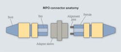
MPO connectors enable parallel transmission, as the multi-gigabit transmission signals are split across parallel fibers and aggregated by the electronic equipment. MPO connectors use alignment pins to precisely align the multiple parallel fibers as they are mated, creating the connection of a male ferrule to a female ferrule. When using MPO connectors, the fibers are "keyed" so you need to recognize the keyway of the adapters to ensure proper polarity.
Each MPO connector has a key on one side of the connector body. When the key sits on top, the connector is in a "key up" position. Each of the fiber capillaries in the connector is numbered in sequence from left to right.
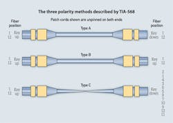
As mentioned previously, with parallel optics, polarity must be addressed to ensure transmit and receive protocol matches the transceiver arrangement throughout the link. TIA-568 shows three methods for maintaining polarity with MPO assemblies. In the diagram, the MPO patch cord assemblies are shown with both ends unpinned. Note that these patch cords will have 12 fibers, sometimes ribbon fibers, going from connector to connector.
The Type A MPO assembly shows a key-up-to-key-down method, whereas Type B has fibers in a different location for a key-up-to-key-up approach. Type C has fiber positions 1 through 12 and the key-up position on the left; the individual fiber pairs are crossed within the cable, between the two connectors. As shown in the figure, the number 2 fiber could be in the first position and the number 1 fiber is in the second position, and so forth down the line. The mating of those connectors must be considered when bringing them together, either into the electronics or connector-to-connector. TIA further describes MPO connectivity methods for 12-fiber links and 24-fiber (2-row) links.
Preterminated assemblies
Many times, MPO connectors and any simplex connectors are provided as preterminated cable assemblies. Preterminated cable assemblies offer several advantages. The polish is pristine from a factory termination. The assembly has been tested and has good results. Test results are typically packaged with the assembly, so they are visible as you're receiving it. There are no field tools required because you're purchasing the preterminated cable ready to be placed in the building pathway. Training is minimal and focused on the handling and pulling of cable and protecting the connectors.
Cleaning and acceptance
There is plenty of information available on the importance of cleaning connectors properly before installing them, so this article does not go into this aspect except to say that connectors-even new ones-should be cleaned properly using cleaning kits with specialized fluids and wipes. Dirt, debris or oils from the technician's fingers will all affect performance.
Once the network is complete, it must be tested. Fiber connector performance is prescribed by the ANSI/TIA-568-C.3 specification. While there is much more information on testing available, this article will just address that optical loss test sets are the most common testing method. They measure the attenuation, or light loss, end to end. If a high level of loss is detected, troubleshooting might be required to identify the connector(s) or cable(s) causing the light loss. An optical time-domain reflectometer (OTDR) is often used for measuring the distance, the attenuation and return loss of fibers and connectors, and serves as an excellent troubleshooting device.
Note: Webinars addressing the cleaning, inspection and testing of optical fiber connectors are available to watch on demand on the BrightTalk Channel of the TIA's Fiber Optics Technology Consortium.
Optical fiber connectors continue to offer low-cost, low-loss and reliable connectivity for evolving local area and data center applications. There are a variety of designs and field-termination methods available. As networks move toward higher-density and higher-speed applications, the market is moving toward smaller connectors, like the LC, and multifiber connectors such as the MPO/MTP.
To meet the increasingly tight light-loss budgets of applications such as 40 GbE and 100 GbE, technicians will need to follow the manufacturers' procedures, including properly cleaning and inspection of all connections when performing field terminations. This approach will ensure reliable, high-quality optical fiber networks.
David D. Cook is marketing product manager at 3M Communications Markets Division. He wrote this article on behalf of the TIA's Fiber Optics Technology Consortium (www.tiafotc.org).

