Old school meets new school in fiber connectivity

By Ray Barnes, Corning Optical Communications
Have you ever considered how much more information and what an increase in tools and technology the average person today has to have and effectively use versus 20 years ago? After all, today almost anyone can learn the skills necessary to complete almost any task, from growing tomatoes in your back yard to replacing a part on the family car. All it takes is a few searches of the internet via smartphone or computer, then watching and reading the volume of articles and videos that cover the subjects. Technology and information delivery have clearly expanded our ability to take on and successfully complete new and novel tasks. In many cases, it is not only a convenience to have these abilities, but in most fields today it is a necessity. Several years ago, we might not have attempted many tasks or jobs without some type of normal training or apprenticeship. This training or apprenticeship, while often costly and time-consuming, was the only way to effectively gain the proficiency necessary to do a job correctly. This was particularly true if the job involved terminating fiber-optic cables with optical fiber connectors.
In the early days of fiber optics, fibers were terminated with complicated epoxy and polish products using procedures that had a difficulty somewhere between assembling a piece of furniture and painting a Picasso-a balance of following many steps while applying the proper amount of touch and feel to prevent breaking a fiber and scrapping the connector along the way. Even with the difficulty, there are still many field-polishing kits in service today in the hands of elite craftspeople who have achieved mastery over the course of many years and many thousands of terminations. But the difficulties in mastering an epoxy-and-polish termination method have led to alternative methods for optical fiber termination that in many ways are simpler, faster and more cost effective. These include splice-on connectors and pigtails as well as no-epoxy, no-polish connectors. Although all of these optical termination methods result in similar outcomes, it can become cumbersome because there are many vendors and termination kits, which lead to a somewhat diverse and proprietary landscape of options. While this diversity is certainly good for competition, it presents a challenge to installers, contractors and end users.
During extensive voice-of-customer activities that we at Corning Optical Communications have conducted, installers and contractors have repeatedly called for simpler, easier-to-use and more-intuitive product installation procedures and practices. There is also clearly a desire to standardize on one installation method. The use of different toolkits for different applications is counter to these requirements and often requires a fiber technician to be proficient with several different termination methods, each with its own training requirements, to become proficient. Furthermore, this proficiency must be maintained over time even though it can be weeks or even months between fiber installations for many fiber installers.
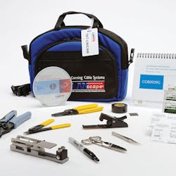
We used this voice-of-customer feedback and also focused on other drivers to evolve the installation toolkit for our UniCam high-performance connector. The kit leverages technologies brought about by the smartphone revolution to deliver customer value. The original kit was basic; it included a score-and-snap cleaver and a basic mechanical assembly tool that simply turned the locking cam of the connector and provided a “flip lever” for the final crimp step of the process.
Although very basic, the kit provided just what was needed at that time in the evolution of fiber connectivity. The then-current fiber-connector technology was quick and easy to install without the expense of a fusion splicer or the extensive training required for proficiency with the epoxy-and-polish connector. Chris Jordan with MTS Services recalls the original UniCam kit: “UniCam was an avenue to get more people’s hands on fiber. It made fiber a more-level playing field so that fiber wasn’t as much of a specialty and more people could be trained to do it. When I started in 1999 we had two trained fiber techs; today we have at least 30 technicians that could do it.”
Even with the early success of that no-epoxy, no-polish connector, there was clear value in making the termination process even easier. In 2000 a kit was introduced that included a continuity test system (CTS). This system used a visual fault locator (VFL) coupled into the connector being installed, which created a glow of the translucent cam on the connector. If the fiber inside the connector was installed correctly, the cam glow would dim significantly upon activation.
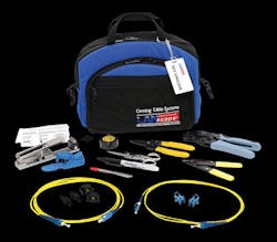
This was a game-changing innovation because it was the first time a no-epoxy, no-polish connector kit could provide real-time feedback that the connector was properly installed at the point of installation. “The use of the CTS was the biggest thing because with the light I knew when I cammed it that I wouldn’t have to open up the housing during testing. The light gave me immediate confirmation that the connection was good,” said MTS’s Jordan.
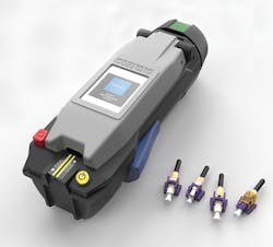
The CTS’s main value for the customer was in providing real-time feedback; however the value was limited by the subjectivity in visually judging whether the VFL cam-glow had dimmed enough when the connector was activated. In an effort to reduce the subjectivity, the VFL, CTS adapters and jumpers were integrated into the tool and a photodetector was added. This reduced subjectivity because the tool could make a determination of whether the cam glow was diminished sufficiently and provide a pass-or-fail indication to the installer. This innovation not only provided instant confirmation that the fibers were properly mated inside the connector, but it also provided a compact handheld tool that could be used in tight work environments where no work surface was possible. Travis Atwater with Intellicom Inc. commented, “Toolkit changes have led to a faster process and makes it easier to move from job to job. I like the handheld tool because you can use it when you don’t have a table.”
Focus on the installer and contractor drove further enhancements, to create a toolkit that is simple, easy and intuitive to use, reduces the amount of initial and ongoing training required for proficiency and provides real-time feedback to the installer so that problems are identified early and do not complicate final system testing. The introduction of a latest-generation type of toolkit continues to deliver value by bringing the connector installation kit into the age of the smart device. The new installation tool uses onboard intelligence in the form of sensors, software, microprocessors and videos to guide the installer through the entire installation process. Gone are the days of forgetting the connector boot on the first connector of the job. The installation tool has become the trainer itself. When powered on, the newest-generation installation tool immediately conducts a status test. With a combination of position sensors and switches within the tool, and onboard software and processing, it immediately knows if a connector is loaded, what type of connector is loaded, and the current step in the installation process. With this information, the installation tool provides the appropriate feedback via onboard video and a display built into the assembly tool to guide the installer on what to do next. This onboard guidance results in several key benefits for the contractor and installer.

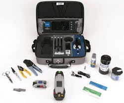
One tool fits all
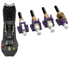
An example of a toolkit on the leading edge of capability is Corning Optical Communications’ UniCam High-Performance Toolkit 2. This one kit can be used to install all three of the most common connector types (LC, SC, ST) and all fiber types. This capability greatly simplifies fiber termination operations for contractors and allows them to purchase, train and maintain one kit for all fiber terminations. “We try to pick the right products for the application, and UniCam fits a lot of applications,” said George Demartz of Premiere Communications. The tool does not need to be modified in any way when the installer changes from one connector type to another, or from one fiber type to another. Using onboard sensors, the tool automatically knows what connector and fiber type is being installed when the connector is loaded into the tool. This allows the tool to adjust internal parameters and videos to ensure that the installer completes all necessary steps to ensure a passing connector.
When it comes to ease of use, no-epoxy, no-polish connectors have always been at the forefront. With the new High-Performance Toolkit 2, the level of intuitiveness and ease of use is so high that the installation tool does virtually everything but install the connector for you. The design process of the high-performance tool relied heavily on feedback from installers and specifically understanding where installers were having difficulty with existing toolkits. Aspects of the installation as fundamental as where to put the connector in the installation tool were not very intuitive and required some level of dexterity. The new installation tool uses basics-colors, shapes and symbols-in intuitive ways to make the connector installation easier.
The three most common installer requests concerned connector loading, fiber insertion, and VFL adapter selection. For connector loading, a combination of shape and color results in a connector load adapter that not only matches the shape and color of the connector load area in the tool, but also the same shape and color combination could be used for all connector and fiber types. Color and shape also ease fiber insertion into the connector. The high color contrast of black-on-yellow creates a “runway” that consists of a precision V-groove, allowing the fiber simply to be laid into the V-groove and then pushed into the connector, which is held in alignment by the tool itself. Finally, VFL adapter selection is simplified with the addition of a VFL adapter “toggle” that is clearly marked according to connector type, and allows one to switch between the LC connector and SC/ST connectors as easily as flipping a switch.
Training by doing
During feedback sessions, we learned from owners and senior managers of contracting firms that their workforce of technicians was changing. Instead of having one or two technicians that were fiber-qualified, they prefer to have fiber-termination capability across nearly all of their workforce. This gives the contractor the ability to flexibly deploy technicians across a wide variety of jobs, whether the optical fiber termination component is small or large. Having this flexibility in the workforce relies not only on an installation process that is easy and intuitive, but it also relies on a process in which the initial and maintenance training is not cumbersome to the organization. When asked about the way training requirements have changed over the years, Premiere’s Demartz said, “Training is a lot simpler today due to UniCam’s simplicity. You can sit with a tech with intermediate skills and in four hours they can complete UniCam installations with the best of them. Seventeen years ago it would have taken a solid one to one-and-a-half days to train. The internet has changed training in a good way; the guys learn a lot from watching the videos on YouTube before they even get any sit-down training.”
Corning’s philosophy regarding training using our High-Performance Toolkit 2 is that the toolkit itself should provide all the training necessary to be proficient at installing optical connectors. This is accomplished by first taking advantage of the intuitiveness built into the tool functionality and controls, and second providing instructional videos, linked to the installation process by the onboard sensors and played directly on the installation tool’s built-in display. The tool not only knows where the installer is in the installation process, but also prompts the installer on what to do next. It does so from the moment the installer presses the power button, and continues until all connectors are installed or the unit is powered off.
Another key to self-training capability is an interactive video display that is incorporated into the toolkit case. This video display allows the installer to reference detailed installation videos and tips, even when no internet access is available.
Performance is key
It also became apparent to us that the connector toolkit is not simply a tool to get connectors on the ends of a cable; it is a business-enabler. How well the toolkit does depends on one attribute: performance. Optical fiber connector performance is typically measured in terms of installation time, scrap, and insertion loss. With the built-in guidance of the High-Performance Toolkit 2, scrap connectors resulting from initial training and initial startup at a new jobsite are greatly reduced, if not eliminated, because missing steps such as installing the boot on the fiber or failing to crimp the connector should not occur. Additionally, the fiber-insertion runway on the tool reduces scrap associated with damaging a cleaved fiber or breaking a fiber on insertion into the connector.
Another key aspect of performance, which you will not find on a specification sheet, is what we call “link yield.” An optical fiber link loss budget or maximum is calculated by adding all the components contributing to loss in an optical link. For example, in a simple link it may be the attenuation of a length of fiber plus the attenuation of the connectors on the ends of the fiber. In more-complicated links, there could be splices or attenuators. The point is, the real measure of performance is how well the final optical link attenuation test compares to the calculated maximum link loss budget; the percentage of links that test within this budget is called the link yield. Of course, higher link yield is better. While low insertion loss of individual connectors is important, link yield is a better measure for the performance of an installation method. The reason is that it is straightforward to isolate and repair connectors that test out-of-spec during installation, but once the connectors are installed in a link and those connectors are plugged into an adapter panel in an optical-fiber housing, it becomes much more difficult to troubleshoot, isolate and repair a connector in a link that doesn’t pass the link attenuation test.
For this reason, the built-in CTS system is critical. As previously mentioned, in the older-generation tool a VFL was used to illuminate the connector and a photo detector was used to measure the light emitted from the glowing cam area of the connector. The level of light focused on the photo detector then would induce a voltage level across the device, which was compared to a factory-set voltage level in the tool. If the voltage level was below the set point, the tool would provide a green LED, indicating that the VFL glow dimmed sufficiently to conclude that the fiber stub in the connector and the cleaved field fiber being terminated were in continuity, or physical contact, following activation of the connector. If the voltage level was above the set point, the tool took this to mean that the VFL light did not dim sufficiently and that the fiber stub and field fiber were not in contact. This was indicated by a red LED in the tool.
While the CTS system did a great job ensuring continuity within the connector, the voltage level set point remained the same regardless of the connector type or fiber type being used. Consequently, the tool was very good at ensuring continuity within a connector, but not as good at ensuring that the connector would pass when tested in an installed link. The new installation tool incorporates several improvements to the built-in CTS. First, the placement of the photodetector is optimized to ensure the VFL light from the connector is more tightly and uniformly focused onto the photodetector. Second, the voltage set point within the tool can now be optimized to the connector type and fiber type being used. Furthermore, this set point is software-defined and automatically set based on the connector being installed.
The result: By ensuring high-loss connectors are identified and fixed during installation, less time will be expended and fewer connectors will be scrapped in troubleshooting and repair of links that test high during the final certification test.
Speed of deployment, which is closely tied to installation time, has always been a key differentiator among fiber-optic connectors. When we first introduced the UniCam, its typical installation time was about two minutes. With the introduction of the handheld installation tool, typical installation time was approximately one minute, and even less than a minute with particularly skilled installers. While speed is important, many contractors have told us that two minutes is a very fast and acceptable installation time. So we chose not to focus on the fact that in lab tests our newest tool is about 15 percent faster, certainly providing sub-one-minute installation time. When it comes to speed, everyone knows the fastest way is to do it right the first time.
Ray Barnes is manager of LAN market development for Corning Optical Communications (www.corning.com).

