Sorting out fiber-optic cable options
By Patrick McLaughlin
For a cabling system end-user organization that is getting ready to implement a fiber-optic infrastructure for the first time-or for the first time in a long while-the considerations that go into choosing the most appropriate optical medium are more plentiful than ever. This article will focus on technologies and applications surrounding multimode fiber. The merits of singlemode fiber in data center, campus and enterprise networks should not be slighted and will be addressed separately in other articles.
Up until the mid-1990s the options were fairly straightforward. Singlemode fiber provided practically unlimited bandwidth and extremely long distance. For multimode fiber, two primary versions were available, one with a 62.5-micron core and another with a 50-micron core. Outside of telecommunications providers, the 50-micron version gained popularity among some government and specifically military applications. But in commercial and enterprise environments, 62.5-micron fiber was the more-popular option.
Because of its larger core size, 62.5-micron fiber offered a greater numerical aperture (NA), an optical characteristic that determines the fiber’s ability to accept and carry light. At that time, light sources within optical transceivers were light-emitting diodes (LEDs). Compared to the laser-based light sources used today, LED sources emitted broad light beams; some of the emitted light entered the fiber core and some did not. A 62.5-micron fiber’s higher NA, enabled by its larger core, allowed it to capture and transmit more light than a 50-micron fiber, with a lower NA, could.
Gigabit game-changer
The advent of gigabit-speed optical transmission, and Gigabit Ethernet in particular, changed the landscape of multimode fiber specification. Gig speeds require the use of vertical cavity surface-emitting lasers (VCSELs), which generate narrow light beams, in contrast to LEDs’ broad beams. As such, an optical fiber’s numerical aperture no longer played an important role in determining a fiber’s information-carrying capacity. Furthermore, VCSELs that generate Gigabit Ethernet signals operate in the 850-nanometer operating window. Much of the 62.5-micron fiber deployed through the mid-1990s was FDDI-grade (Fiber Distributed Data Interface) fiber, best equipped to support LEDs that operated in the 1300-nm window because the fiber has a higher bandwidth at 1300 nm than it does at 850 nm. That FDDI-grade fiber could, and still can, support 850-nm VCSEL-based Gigabit Ethernet, but to a shorter distance than other grades of fiber.
For its part, 50-micron fiber’s bandwidth at 850 is higher than 62.5-micron fiber’s (500 MHz.km to 200 MHz.km), enabling it to support 850-nm-based Gigabit Ethernet for longer distances than 62.5-micron fiber-550 meters to 275 meters.
The tenfold leap in speed from Gigabit Ethernet to 10-Gigabit Ethernet gave rise to the development of Om3 fiber. As the entire fiber-based 10-Gigabit Ethernet ecosystem was coming to life, it became apparent that a need existed for a better-performing multimode fiber that could provide long-distance 10-GbE transmission in the 850-nm window. To meet the industry’s need, manufacturers of optical fiber developed a 50-micron multimode fiber that was produced in such a way that it was optimized to support 850-nm-generated signals to long distances. This type of fiber is commonly referred to as “laser-optimized 50-micron multimode,” although it is optimized specifically for the 850-nm window, as opposed to being optimized for any laser source in any operating window.
OM nomenclature
With the emergence of this new multimode fiber type, and the practical need to distinguish each type from the others, eventually the industry adopted the “OM” nomenclature defined in the ISO/IEC 11801 specification. The three types described to this point are designated Om1, Om2 and Om3. While multiple criteria determine a fiber’s grade, its minimum bandwidth at 850 nm, measured in MHz.km, is a significant criterion. Specifically, Om1’s 850-nm bandwidth is 200 MHz.km; Om2’s is 500; Om3’s is 1,500.
The aforementioned bandwidth performance levels are measured using what is known as the overfilled launch (OFL) method. Another bandwidth-measurement method, called effective modal bandwidth (EMB), is a calculated measurement. EMB bandwidth exists for Om3 fiber, but not for Om1 or Om2. Om3 fiber’s minimum EMB is 2,000 MHz.km.
As a practical matter for user organizations, Om1 fiber can support 1000Base-SX-the 850-nm variant of Gigabit Ethernet-to 275 meters. Om2 provides 550 meters of support. When speeds go up to 10 Gbits/sec in the form of 10GBase-SR, Om1 supports 33 meters, Om2 supports 82 meters and Om3 supports 300 meters.
Notably, however, the ANSI/TIA-568.3-D Optical Fiber Cabling Components Standard was approved and released for publication in February. Table 1 in that standard no longer includes Om1 or Om2 fiber performance grades. They have been moved to the standard’s annex and are no longer recommended for use in fiber-optic installations. Om3 is now the minimum recommended performance grade.
That relegation to the standard’s annex is unlikely to prevent users from continuing to purchase and use Om1 or Om2 fiber-optic cable. Om3 is backward-compatible with Om2 and could be placed into an existing Om2 cabling plant without sacrificing performance. However, Om1 fiber, with its 62.5-micron core, cannot be combined with a higher grade of multimode fiber because that higher grade’s 50-micron core means high losses will be induced when a signal crosses from the 62.5-micron to the 50-micron portion of the cabling plant.
History repeats
To some extent the technological development that led to Om3’s development repeated itself and resulted in the introduction of Om4 fiber. After Om3 fiber was established and its guaranteed 10GBase-SR distance was specified, fiber manufacturers developed better-performing fibers with higher bandwidth, better loss performance, and therefore the ability to support longer-distance 10G. With Om3 being the highest-performing standardized multimode fiber, vendors, users and others in the industry frequently used the term “Om3+” to refer to fibers with bandwidth and performance levels that exceed those specified for Om3.
Meanwhile the development of 40- and 100-Gbit Ethernet was shaping up to shorten the distances Om3 could achieve, akin to but not quite as dramatic as the shorter distances to which Om1 and Om2 can support 10G. The need for a higher-performance, longer-reaching multimode fiber ultimately resulted in the specification of Om4.
When the TIA approved its Om4 fiber specification in 2009, CommScope’s Paul Kolesar explained in an article we published, “Not everyone could wait for the new Om4 standard to emerge. Early adopters have been enjoying Om4 capability for more than five years. By the time the TIA committees were voting on the new Om4 specifications, hundreds of data centers around the world were already running smoothly with next-generation, Om3-exceeding fiber cabling that would later meet Om4 standards-most of which had been installed years ahead of time … Some of the same laser-optimized fiber cables that exceeded Om3 standards now meet TIA’s Om4 standard. The Om4 standard adopted the most-stringent of the proposals that were submitted for consideration, so cables that adhere only to less-stringent specifications cannot claim compliance.” (“Om4 fiber cabling standard for next-generation data centers,” October 2009)
Om4’s minimum EMB at 850 nm is 4,700 MHz.km, and its minimum OFL bandwidth at 850 nm is 3,500 MHz.km. Like Om1, Om2, and Om3, it has a minimum OFL bandwidth of 500 MHz.km at 1300 nm. Om4 supports 40GBase-SR4 and 100GBase-SR10 to 150 meters; Om3 supports both to 100 meters.
While this article addresses optical fiber, the importance of connectivity in high-speed links cannot be ignored. In an optical link of any distance, the fiber will contribute some signal loss; points of connectivity in those links are more-significant contributors of loss. The ability to extend transmission distance at a given speed (e.g. 10 Gbits/sec) is enabled by decreasing connection losses. Nonetheless, the optical fiber plays a significant role in accepting and carrying optical communications’ light pulses, and the information in this article details them.
Multiple wavelength capability
Over the past approximately 18 months another multimode fiber type has emerged and advanced significantly toward official standard specification. Dubbed wideband multimode fiber (WBMMF), the medium is being referred to by some as “Om4+” reminiscent of the decade-earlier “Om3+.” However, the differences between WBMMF and Om4 are more significant than those between Om4 and Om3. Specifically, WBMMF is being developed to support optical transmission at multiple operating windows through what is known as wave-division multiplexing (WDM). Whereas the 850-nm window has been primary, and Om3 as well as Om4 fibers are bandwidth-optimized to support transmission within that specific window, WBMMF will support transmission in four separate operating windows.
The essential value proposition of WBMMF is that rather than needing four separate fibers to transmit four distinct optical signals, the signals can be sent down a single fiber over four separate operating windows. Om3 and Om4 fiber have been optimized to transmit signals in the 850-nm operating window exclusively, and those fibers’ bandwidth performance at other operating windows is less than its bandwidth performance at 850 nm. As a practical matter, Om3 and Om4 fibers can support high-speed transmission at 850 nm only. WBMMF will support high-speed transmission at four wavelengths. One application of WBMMF could be for each optimized wavelength to provide a 10-Gbit/sec “traffic lane,” enabling a duplex WBMMF connection to accommodate 40-Gbit/sec transmission. Another application could be for each lane to support 25 Gbits/sec, enabling a duplex WBMMF connection to accommodate 100-Gbit/sec transmission. Scaling that 25-Gbit/sec/lane model would allow 400-Gbit/sec transmission over 8 wideband multimode fibers.
Accomplishing objectives like these requires development of transceivers to perform WDM. While standards efforts are ongoing and the exact wavelengths have not been finalized, standards makers’ efforts have been to specify a WBMMF that is optimized at four wavelengths roughly between 850 and 950 nm. In general, the wider the spacing between the optimized wavelengths, the more readily transceiver manufacturers can produce WDM equipment economically.
WBMMF’s optimization at 850 nm will make it backward-compatible with Om4. WBMMF is in production and available for purchase today. Its promise of Om4 backward compatibility means users can specify WBMMF and use it for Om4-based applications today, and in doing so provide themselves with the capability to support WDM applications in the future.
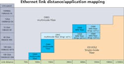
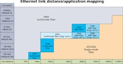
At the BICSI Winter Conference held in early February, OFS multimode optical fiber product manager John Kamino delivered a presentation titled “Next Generation Multimode Fiber.” In that presentation he described the drivers behind the need for more-capable multimode fiber, the current standards scene within the TIA as well as the IEEE (Ethernet) and INCITS (Fibre Channel), and other detail on the latest developments in multimode fiber production and use.
The color-coded illustration in this article showing Ethernet link distances and the most appropriate fiber types for them comes from Kamino’s presentation. That presentation can be accessed and downloaded at bicsi.org.
We will continue to track the standards and technological developments of multimode optical fiber, and will report our findings periodically.

