Zone cabling and coverage area planning
By Valerie Maguire, Siemon
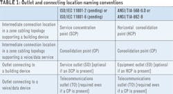
Zone cabling is ideal for supporting convergence of data and voice networks, wireless (WiFi) device uplink connections, and a wide range of sensors, control panels, and detectors for lighting, security, and other building communications. A zone cabling design consists of horizontal cables run from the floor distributor in the telecommunications room (TR) to an intermediate connection point that is typically housed in a zone enclosure located in the ceiling space, on the wall, or below an access floor. The name of this intermediate connection point depends on the types of end-point device connections it serves, and on the applicable regional structured cabling standard (see Table 1). For convenience, this article refers to the intermediate connection location as the service concentration point (SCP). The outlet supporting a building device connection is referred to as the service outlet (SO).
Connections at the SCP are typically facilitated by connecting hardware supporting 2 to 96 outlets. Cables are then connected from outlets in the SCP to building devices, SOs, or telecommunications outlets (TOs).
Zone cabling benefits
Zone cabling is a highly flexible infrastructure that is ideally suited for the convergence of voice, data, wireless, and building device applications over one managed network. Furthermore, outlets serving voice/data, wireless, and building device connections can be conveniently combined within one SCP.
Zone cabling solutions support rapid reorganization of work areas and equipment and simplify deployment of new devices and applications. With this type of infrastructure, moves, adds, and changes (MACs) are less costly, faster to implement, and less disruptive because changes are limited to the cabling segment between the SO/TO and SCP instead of the entire length of horizontal cabling. In addition, zone cabling designs allow the option of deploying factory-preterminated and tested trunking cables to support quick implementation, performance exceeding field terminations, and reduced field testing times.
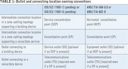
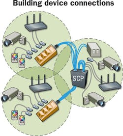
The rendering on the next page shows a zone cabling deployment, depicting a ceiling-mounted zone enclosure connected to SOs that provide connection to fixed WiFi, IP surveillance, and electronic display devices. The same SCP may connect to TOs in work areas and common spaces for phones, computers, and docking stations. Siemon offers a wide range of zone enclosures supporting up to 96 outlets for ceiling, underfloor, and wall-mounted SCP applications. Products that may be used to provide SO and TO connections include 3- and 6-port boxes and 1-, 2-, 4-, and 6-port outlet boxes.
The major benefit of zone cabling is its ability to provide an easily accessible intermediate connection point. Being able to locate zone enclosures in an access floor, ceiling, on the wall, or within modular furniture enables convenient access to these connections. The deployment of strategically placed zone enclosures throughout a building space creates a flexible, futureproof infrastructure for data, voice, building devices, and wireless access points (WAPs).
What is a coverage area?
According to ISO/IEC and TIA standards, the area served by a device is called its coverage area. For the purpose of this article, the term “coverage area” is extended to describe a space that may serve multiple devices and their respective coverage areas. We recommend that device coverage areas be planned to have a radii no greater than 13m to ensure support of fifth-generation (IEEE 802.11ac) and future WiFi. While other devices may have wider coverage areas, the area served by a WAP is generally the smallest of all building device applications. This practical guidance ensures generic support of all current and future building device and WiFi applications with a single zone and coverage area design.
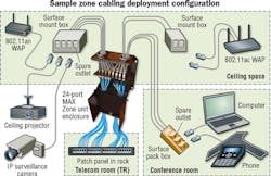
The illustration to the right shows an example of a ceiling-mounted zone enclosure functioning as the SCP. It is centrally positioned within four coverage areas, providing connections to four, 2-port SOs serving IEEE 802.11ac WAPs, each having a coverage area radius of 13m. Note that the 26-meter diameter of each WAP coverage area is larger than the square grid coverage area pattern to ensure no gaps where the coverage areas intersect.
We recommend that the number of connections in the zone enclosure should not exceed 96. This recommendation harmonizes with IEEE 802.3 Type 2 and Type 3 Power over Ethernet (PoE) maximum bundle size limitations and is aligned with guidance provided in ANSI/TIA-862-B Structured Cabling Infrastructure Standard for Intelligent Building Systems, both of which optimize zone enclosure access by eliminating over-congestion in the SCP. The size of the zone area should be decreased if more than 96 outlets are required at the SCP to support initial and projected device connections over a ten-year period.
Dividing the coverage areas between multiple SCPs provides optimum accessibility, which translates to lower cost for MACs. For example, the pending international standard ISO/IEC 11801-6 Information Technology - Generic Cabling for Customer Premises - Part 6: Distributed Building Services, states that the SCP should be limited to serving a maximum of 36 service areas, each of which can have one or more connections. Since “should” is not a normative requirement, it is left to the discretion of the infrastructure designer to determine the maximum number of connections in the zone enclosure.
Location of coverage areas served by zone enclosures
Unless the TR has limited accessibility, an SCP does not provide significant added benefits if it is located within 17m of the TR. Coverage areas that are in close proximity to the TR can be connected directly to the floor distributor without passing through an SCP. We therefore recommend that zone enclosures be positioned at least 30m from the TR.
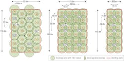
Different patterns may be used to lay out arrangements of hexagon- or square-shaped coverage areas, with the intent that zone enclosures should be located within their associated grouping of coverage areas. The figure above shows examples of coverage areas arrange in hexagon, grid, and leg deployment patterns. For simplicity, these examples depict only one SO in the center of each coverage area. In real-world deployments, coverage areas typically contain multiple telecommunications outlets and service outlets connecting to a wide variety of devices. The area comprising multiple coverage areas served by one zone enclosure is called the zone area. Representative zone areas for SCPs are highlighted in various colors in the figure. Note that the figure does not show the location of the TR, which can affect the arrangement of coverage and zone areas.
A hexagon deployment pattern (sometimes referred to as a “honeycomb” pattern) typically serves four to five, 425m2 hexagon-shaped coverage areas and may be most suitable for large, open spaces such as open office, industrial, retail, and warehouse environments. If the coverage area radius is 13m, then an SCP should ideally serve a zone area of approximately 2000m2 (excluding unused portions of coverage areas around the perimeter). This pattern may be best suited for supporting up to 96 outlets at the SCP.
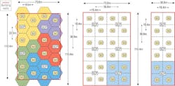
A grid deployment pattern typically serves four, 350m2 square-shaped coverage areas and may be most suitable for large building spaces supporting classrooms, enclosed office spaces, patient rooms, etc. In this configuration, each SCP will serve a zone area of approximately 1400m2 with zone enclosures positioned above, along, or below building hallways to facilitate easy access to the SCP. This pattern may be best suited for supporting 36-96 connections at the SCP and for designs where the zone enclosure is located below access flooring.
A leg deployment pattern may be most suitable for long and narrow structures or wings whereby zone enclosures are positioned in a line above, along or below building hallways. Each zone enclosure typically supports, four, 350m2 coverage areas similar to the grid deployment pattern. Typically, a leg coverage area pattern featuring 24 to 96 outlets housed in a zone enclosure positioned along a wing or hallway is sufficient to provide desired coverage.
No single coverage area pattern is best for all zone cabling designs. As shown in the figure above, the main advantage of a hexagon deployment pattern is that it supports the least degree of overlap between coverage areas, potentially resulting in fewer zone enclosures and fewer coverage areas in the overall cabling design. Because the size of the zone area served by a hexagon coverage area deployment pattern is larger than that of a grid coverage area pattern, it may be necessary to divide the area into more zones or use a combination of zone area patterns to meet the recommendation of no more than 96 outlets per SCP. In real-world infrastructures, a combination of patterns may provide the most economical and functional design.
A site survey report can be extremely helpful in determining the best coverage area layout. The following are true in general.
- The 1400m2 zone area served by a grid or leg deployment pattern of four, 350m2 square-shaped coverage areas is most accommodating of one zone enclosure being capable of housing all required SCP connections in a highly automated building.
- The 2000m2 zone area served by a hexagon deployment pattern of four to five 425m2 hexagon-shaped coverage areas is most accommodating of one zone enclosure being capable of housing all required SCP connections in a conventional or moderately automated building.
- The 3000m2 zone area (excluding unused portions of coverage areas around the perimeter) served by a hexagon deployment pattern of seven or eight 425m2 hexagon-shaped coverage areas accommodates one zone enclosure supporting WAP uplink connections with very limited support of other building devices.
Standard ISO/IEC 11801-6 (pending), ANSI/TIA-862-B, and TIA TSB-162-A Telecommunications Cabling Guidelines for Wireless Access Points, all provide useful information on hexagon and grid coverage area deployment patterns.
Service outlet use within coverage areas
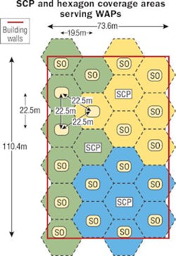
Each coverage area may have multiple SOs, TOs, and direct connections from SCPs to building devices. The figure to the right depicts two coverage areas serving WAP, IP-camera, and IP-lighting connections via SOs and one coverage area containing a zone enclosure serving security camera and WAP connections via SOs and direct connections. SOs in ceiling spaces are typically housed in outlet boxes and available in 2- to 6-port configurations. In some jurisdictions, these outlet boxes may need to be plenum-rated.
ISO/IEC and TIA intelligent building specifications do not require an SO to be present in a zone cabling infrastructure if an SCP is present. However, because building devices can be located as far away as 30m from the SCP, SOs eliminate the need to install long lengths of cable when devices are added. Removing abandoned cable when devices are taken out of service can be just as labor-intensive. We recommend that an SO be used if a building device or WAP is more than 5m from an SCP.
Due to the higher resistance and up to 50 percent higher insertion loss of cable having stranded conductors and much greater sensitivity of higher-AWG stranded cables to elevated temperatures, we recommend that solid-conductor cables be used exclusively in spaces that do not have environmental control (e.g. ceilings and warehouses). In temperature-controlled spaces, we recommend that building device connections to an SO or SCP should not exceed 5m if stranded conductor cords are used.
Solid conductor cable assemblies are much less temperature-sensitive and less prone to resistive heating for remote powering applications and support lower parasitic power loss, higher transmission performance, and longer reach in these spaces at ambient temperatures ranging from 20 to 60 degrees Celsius.
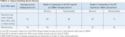
Zone area device density
While arrangements of hexagon-shaped and square-shaped coverage areas are recommended to optimally accommodate most converged cabling networks, coverage areas may range in size to support device coverage area radii from 3m to 30m.
The Internet of Things (IoT) allows objects to be remotely sensed and controlled across a common network resulting in improved efficiency and comfort. Building automation systems enable IoT by providing a structured framework to monitor and control utilities, ambient air, lighting, security and safety. These relationships influence cabling infrastructure decisions such as the number of outlets needed in the zone enclosure at each SCP. Availability of spare ports in the zone enclosure offers the ability to rapidly add new services and reconfigure devices. An assessment of the desired level of building automation and anticipated deployment of building devices as new technologies come available can be used to determine the number of spare ports to be provided in an initial zone cabling design. Because of the rapid advancement in IoT technologies and building solutions that rely on sensors and automation to increase energy efficiency, occupant safety, and comfort, we recommend a minimum initial spare port capacity of 25 percent above initial deployment needs.
ISO/IEC 11801-6 (pending) and ANSI/TIA-862-B provide information on typical building device density for various floor spaces as shown in columns 1 and 2 of Table 2. These recommendations may then be applied to determine the minimum number of device connections required for 2000m2 hexagon pattern and 1400m2 grid pattern coverage area arrangements as shown in columns 3 and 5. For example, an SCP having a minimum 56 outlets can support a floor space of 1400m2 based on 25m2 coverage area per building device. The recommended number of connections to accommodate present and future services based on an allowance of 25 percent spare port capacity is shown in columns 4 and 6.
Outlet density at the SCP can vary throughout a zone cabling design depending on the specific applications that are supported. For example, zone areas containing surveillance equipment, displays, vending machines, and point-of-sale (POS) kiosks in public spaces (e.g. arenas, stadiums, conference center, airport, train station) may benefit from higher outlet density at the SCP.
Mechanical and plant rooms typically have a significantly higher building device density than other spaces. Unlike other independent building devices, the location of air handlers, chillers, boilers, pumps, fans, and compressors can significantly impact the placement of zone enclosures. If the mechanical and plant rooms are within 30m of the TR, we recommend that these connections be home run to each SO without an SCP. Otherwise, deploy one zone enclosure per mechanical and plant room, and have the zone area served by the SCP to these spaces be reduced to no larger than 580m2 (22m x 22m) to ensure that no more than 96 outlets are served by each zone enclosure.
These standards-based device density guidelines can be refined to develop more focused recommendations for the number of connections supported by various coverage area deployment patterns in different building applications. For example, Siemon considered the exact coverage area requirements of specific devices (e.g. IEEE 802.11ac WAPs) and included provisions for spare TOs to accommodate future growth to develop the following guidelines for highly automated and conventional buildings. Emerging technologies, such as remote powering of smart lighting, have unique requirements that may require significantly increased coverage area density and are not factored in to the recommendations below.
Recommendations for highly automated buildings
If the total number of building devices and WAP connections to be supported is unknown in a highly automated building, we recommend the following two deployment configuration approaches.
- The SCP supports 96 connections and serves a grid deployment pattern of four square-shaped coverage areas totaling 1400m2, or
- SOs/TOs supporting 3 or 6 connections are logically positioned throughout the floor or ceiling space to satisfy coverage requirements (SCPs optional).
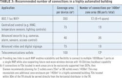
In the first deployment configuration, 96 shielded Class EA/Category 6A or higher-performing ports should be provided at the CSP. The breakdown of building device, WiFi, and telecommunications services supported by this approach is shown in Table 3. This recommendation enables scalability and flexibility to accommodate new building services.
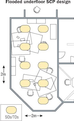
In the second deployment approach, outlets contained in outlet boxes are positioned or “flooded” throughout the floor space in accordance with predetermined building application needs. Typically, this deployment uses an access floor solution and may eliminate the need for zone enclosures. SOs/TOs are positioned approximately 2m apart in a grid pattern in the specific spaces where building device and data connections are required. Port availability at each SO/TO ranges from 3 to 6 ports depending on the number of building device and data connections required. These configurations are sometimes referred to as grid outlet positions (GOPs). The benefits of this approach are as follows.
- Device connections are provided exactly where needed, making it a recommended approach for enterprise, office, and other walled spaces served by network connections located on the wall, below the floor, or above the ceiling; and
- Support of both building device (SOs) and work area connections (TOs) may be integrated into one design.
This solution can be optimized based on advanced knowledge of how the floor space will be used/configured and may benefit from the assistance of comprehensive technical services to determine the appropriate SO/TO density and number of spare ports.
Recommendations for conventional buildings
If the total number of building device and WAP connections to be supported is unknown in a conventional building design, we recommend the following three deployment configuration approaches.
- The SCP supports 24 connections and serves a grid-based pattern of four square-shaped coverage areas totaling 1400m2, or
- The SCP supports 48 connections and serves a hexagon-based pattern of four to five hexagon-shaped coverage areas totaling 2000m2, or
- SOs/TOs supporting 1 to 4 connections are logically positioned throughout the wall, floor, or ceiling space to satisfy coverage requirements (SCPs optional).
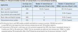
The breakdown of building device, WiFi, and telecommunications services supported per 1400m2 and 2000m2 zone areas is shown in Table 4.
There are many reasons why zone cabling solutions are the ideal network system for automated buildings-from their ability to simplify and reduce the costs associated with MAC work, to the opportunity to leverage intelligent building solutions for green credits, to the option to use factory preterminated and tested trunking solutions for rapid deployment of TR-to-SCP connections and SCP-to-SO connections. The zone and coverage area approaches described in this article may be used as guidelines for infrastructure planning. Since every site is different, there may be additional design factors that need to be considered to ensure adequate coverage of building devices and telecommunications equipment.
To that end, intelligent building experts with specialized experience in the design and deployment of integrated building devices and applications to streamline project engineering can assist in the automated building network design and integration process. This network design expertise provided can result in significantly lowered building-construction costs, reduced maintenance costs, and a safer and more comfortable working environment for building occupants.
Valerie Maguire is global sales engineer at The Siemon Company (www.siemon.com). She received her BSEE degree from the University of Connecticut and actively participates in groups responsible for the development of telecommunications standards. Among other responsibilities, she is the TIA TR-42 appointed liaison to IEEE 802.3.
Service outlet usage for building device and WAP connections
The SO provides a point of connection, administration, and testing for a telephone, computer, building device, WAP, camera, or any other networkable device. The SO is different from the TO, which is the assembly consisting of one or more connectors mounted on a faceplate, housing, or supporting bracket used exclusively in the work area in a commercial building application.
While it is well-known that standards require a minimum of two permanent links/TOs be brought to each work area, practices related to SO usage when supporting building device and WAP connections can be confusing. The following guidance has been excerpted from the ISO/IEC 11801-6 (pending), ANSI/TIA-862-B, and TIA TSB-162-A.
Building device (including camera, security, fire alarm, access control, energy management, HVAC, lighting/power control, audio/video paging, digital signage, service/equipment alarm, and other non-voice/data communications) connections:
- The SCP supports flexibility in a zone cabling topology for fast and easy reconfiguration of building device coverage areas and may be configured as an interconnect (i.e. one patch panel or connecting block) or a crossonnect (i.e. two patch panels or connecting blocks);
- When the SCP is configured in a crossconnect, an SO shall not be installed to ensure that the cabling system serving the building device contains no more than four connection points;
- When the SCP is configured as an interconnect, the use of an SO is optional (i.e. direct connections from the SCP to the building device is allowed);
- If an SCP is not present, then an SO must be used;
- Only one permanent link connection is required to each building device.
WAP connections:
- A minimum of two permanent link connections to each IEEE 802.11ac WAP is recommended to support link aggregation.
We recommend a zone cabling topology consisting of a horizontal distributor, SCP, and an SO to support building device and WAP connections. The SO connection is optional if the building device is located within 5m of the SCP. This design supports ease of coverage area reconfiguration, administration, and cable management, as well as the ability to overlap coverage areas and allocate spare SCP ports to support future building device and telecommunications equipment connections.
Summary of zone cabling recommendations
The bullets below summarize Siemon’s recommended best practices for zone cabling and coverage area design.
Media recommendations:
- Class EA/Category 6A or higher-performing shielded cabling should be in all zone cabling deployments.
- Horizontal cable should be temperature rated to 75 degrees Celsius and connecting hardware should be independently certified to ensure reliable support of remote powering applications.
- Solid conductor cables should be used exclusively in spaces that do not have environmental control (e.g. ceilings and warehouses) for optimum thermal performance.
Technology and design recommendations:
- Device coverage areas should be planned to have a radii no greater than 13m to ensure support of fifth-generation (IEEE 802.11ac) and future WiFi.
- The number of connections in a zone enclosure should not exceed 96.
- TOs located within 30m of the TR should be served directly from the horizontal distributor in the TR (no SCP required).
- A minimum initial spare port capacity of 25 percent above initial deployment needs should be provided at each SCP.
- An SO should be used if a building device WAP is more than 5m from an SCP.
- Building device connections to an SO or SCP should not exceed 5m if stranded conductor cords are used.

