Where's the link?

By Mike Connaughton, RCDD, CDCD, Berk-Tek a Nexans Company
There was a time when the cabling that connected the computer to its peripherals was considered part of the computer system. Seasoned industry veterans (aka “old people”) remember when there were cable products specifically associated with hardware OEMs-the Wang dual coax and the RG58 DEC Cable are examples. If a company was buying or using one of these vendors’ products, the matching cables also had to be used. Therefore, whoever was responsible for managing the hardware was also responsible for the cabling used to connect the devices together. This also (not coincidentally) made it difficult for the customer to move from one vendor to another.
This practice was onerous and customers did not like it. Ultimately, the structured cabling industry replaced this with what we experience today. The cabling infrastructure is now viewed as an independent asset separate from the IT hardware. This has allowed companies to make purchasing decisions for IT and cabling without the concern of being locked-in to the other. This didn’t happen overnight. It has been facilitated by a number of standards and practices that have been created, developed and adopted by the industry over several decades. For 30-plus years, this model has worked well. But a problem is creeping in. To understand the problem, let’s look at how the original challenge was addressed, so that we might see how to proactively deal with the future.
Brief LAN history
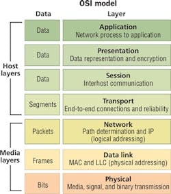
As communication links evolved, the method of specification for the various products has also evolved. Instrumental in this was the advent of computer networking, and more specifically, local area networking (LAN). Among the standards developed to define the operation of a LAN was the Open Systems Interconnection Reference Model (OSI Model). Standardized in 1980, the OSI Model defined seven layers of operation. By using the model, the industry could develop networking functions in a modular fashion and still ensure interoperability.
The bottom of the stack is Layer 1, the Physical Layer. Layer 1 includes the cabling that is used to connect the various pieces of equipment together so that the data can be transported. The next step up on the stack is Layer 2, the Data Link Layer. Layer 2 provides for addressing and switching, so that the data can be sent to the appropriate destination. Layer 3 is the Network Layer, where data can be routed to another network. Layers 4 through 7 deal with software implementations.
It is important to note that although we sometimes assign various physical products to one of the layers, they do not always cleanly fit that way. A Category 6 cable plant resides neatly within Layer 1, but a network switch often contains components that span from Layer 1 to Layer 3. It is the functions that are standardized in the OSI Model, not the devices.
The OSI Model became a powerful tool for customers who had grown tired of the limitations set forth by the single-vendor sourcing model. The new model meant that an end-user could purchase software (Layer 7) and expect it to work on multiple vendors’ hardware (Layer 2). And the hardware could be connected using multiple vendors (Layer 1). Structured cabling now had a home within Layer 1.
Once the OSI Model had been established, TIA then took the task of defining a standard set of cabling parameters. Category 3 was the first product defined as a data transmission media type within the new TIA standard circa 1990. The connector was standardized on the RJ45 and the maximum channel distance was standardized as 100 meters. Layer 1 products were often sourced during building construction and became associated with the facilities. Since BICSI existed as a resource for best practices in the specification and installation of commercial communications cabling, this also helped lead to their importance and popularity.
At the same time, IEEE was defining the networking standards for Layer 2. One standard being developed was Ethernet. It was originally designed to run over coaxial cable (10Base-5), but it was modified to run on the new Category 3 cable as 10Base-T. It quickly became very popular. At the end-user level, these Layer 2 products (switches, network interface cards, etc.) remained in the domain of the IT department.
Over the years, IEEE and TIA have worked in tandem to develop higher data rates and higher bandwidth cabling, respectively. 10Base-T became 100Base, 1000Base, and today we have 10GBase-T. Category 3 became Category 4, 5, 5e, 6 and today we have Category 6A. Through it all, the part that did not change for copper cabling was the footprint of the connector (RJ45) and the maximum distance of a channel (100 meters).
Another effect of this model was the division of responsibility, for cabling versus network design specifications. The end-user ended up having “cabling people” and “networking people” on their staff. Each group of people used their own set of vendors and supply chains to specify and source their materials. And they each only needed a very basic understanding of what the other people were doing.
This system has worked very well for the enterprise LAN. So what’s the problem?
What’s the problem?
The problem started in the 1990s when the bandwidth limitations of an unshielded twisted-pair (UTP) network began to be experienced. Multimode fiber was added to the TIA standard as an option for backbone connections where the extended distances could not be served by copper. Initially the distance limit was 2 kilometers. As time went on, singlemode fiber was added, for still-longer distances, as were various multimode fiber options. Unlike copper, there was never a fixed standard on the connector type or channel distance. Sometimes it could reach a 500-meter link maximum with SC connectors, and other times it could be a 150-meter link maximum with LC connectors.
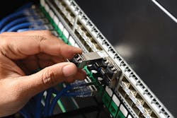
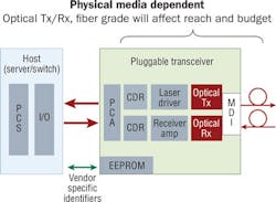
In fiber switches, it is common to use pluggable transceivers. This is done for a variety of reasons, but one is cost. If the customer only needs 10 ports, they can pay for just the ones they need. As more capacity is needed, they can purchase additional ports. But even though the transceiver is plugged into the switch, it is part of Layer 1 in the OSI Model. Not only is it part of Layer 1, but most of the transceiver is part of the physical media dependent (PMD) portion of Layer 1. This means that the transceiver and the cable types have to match. The Physical Media Dependent illustration visualizes what is explained here. However, because the transceiver is physically plugged into the switch, it has always been considered the networking group’s responsibility.
Until recently, this imperfect procedure was more of an annoyance than a problem. With multiple fiber types, multiple operating wavelengths, and multiple connectivity options, the number of solutions seemed limitless. But since the data rates in the enterprise are relatively low, and the pace of change was manageable, a decision could be made to satisfy the demands of the business in a reasonable amount of time.
But the problem has become pronounced in the data center. The data center has two specific attributes that have led to unintended additional challenges.
The data rates are higher. Because the data center is the aggregation point of a significant number of transactions, higher data rates are needed to ensure that there is not a bottleneck. These higher data rates have forced a significant number of connections out of the realm of copper and into optical fiber.
The pace of change is exponentially higher than in the enterprise LAN. This does not allow the time to alter physical cabling layouts in between changes in data rate. Many data centers have seen their switch-to-switch connections migrate from 1G to 10G to 40G in the span of five years. A proliferation of transceiver types has been developed to address many specific applications.
A real-life example of the situations follows, to demonstrate the challenges faced in today’s data centers. (The names have been changed to protect the innocent.)
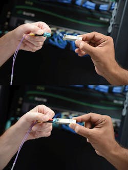
Company A has a data center. Marsha is the facilities manager and is responsible for the data cabling. She has designed a cabling plan that has migrated from 1G into 10G. Anticipating the 40G requirements defined by IEEE 802.3ba (40GBase-SR4), she used a cassette-based platform to allow for the transition from LC connectivity of 10G to the MPO connectivity of 40G. The design incorporated several links that crossed from one data hall to another and therefore had additional patches.
Greg is the network manager. As the migration to 40G switches was about to commence, his hardware vendor recommended that they change to a new unique transceiver solution that used LC connectivity. This appeared to be a great idea because it would mean that Marsha would not have to change any of her connectivity. However, he did not consult with Marsha, because the hardware decisions are his to make.
When the 40G switches arrived, Marsha was surprised by the connectivity choice because it limited her power budget. This created problems for the longer runs. She was forced to start making unplanned changes to the cable plant to accommodate the new technology. Marsha was not happy with Greg.
The point of the story is not that Greg did something wrong. He did what he was expected to do, what he has always done. The point is that his decisions are no longer independent of Marsha’s. Structured cabling was built on the premise that the IT department and the facilities department could act independently. This example is one of many that shows why this is no longer the case.
And as with the old Wang coax, the IT equipment manufacturers are using their influence to create product “tie-ins.” Instead of the cable, however, it now pertains to the optical transceiver. Even though this is an independent device, many manufacturers attempt to force the end-user to use their branded version.
And depending on the recommended version, this can lead to conflicts with the cable plant (or other pieces of equipment).
What should Marsha and Greg do?
If we think about the original objective of the OSI Model, it was to allow various components of a networking system to be specified as a module. In practice, for twisted-pair copper-based systems, the structured cabling/network equipment worked well. The physical application of the cable was fixed and the channel bandwidth simply had to match the data rate.
But for fiber-based systems, it is not as clean. This is true in all parts of the network, but as stated earlier, it is most apparent in the data center.
So let’s ask the question: What does the network manager (Greg in the example of our story) need? Greg needs to have a 40G connection from Rack A to Rack B. From a Layer 2/3 perspective, that is all that matters. He still has the responsibility and complete control to define his needs and select equipment vendors for things like switches, routers, servers, etc. Instead of defining the form of the data rate, he simply specifies the speed.
With that direction, the facilities manager (Marsha) can determine the most cost-effective solution. Marsha can take the following into consideration.
- Maintaining the existing cable plant
- Cost of replacing with new cable plant
- Impact of transceiver options on either existing or new cable plant
- Road map of future technology changes
By shifting the single component (pluggable transceiver) from Greg to Marsha, the organization can make its decision much more efficiently. Greg does not have to worry about the variety of fiber and transceiver options, nor the impacts that they have on each other. And Marsha can manage the entire optical link, from transceiver to transceiver, which is all within Layer 1. Her experience with fiber and connectivity options puts her in a better position to determine which transceiver options are the most appropriate.
The new way
In this model, the service delivery that facilities management (Marsha) provides matches the original expectation of Layer 1 of the OSI Model. The complexities of optical fiber types and their interaction with various PMDs can be managed by a single group. Because the performance of these two products relate to each other, a single dollar value can be assigned to various combinations to determine the best option. And this decision will seamlessly integrate into the Layer 2/3 equipment specified and purchased by IT.
Along with more direct economic decisions, this can also lead to improved supply chain logistics. These include the following.
- Common sourcing provides better supply chain economies.
- Analysis of bills of materials will highlight mismatches (in type or quantity) before orders are placed rather than at the time of install.
- Project tracking and receiving become easier to manage.
As anyone reading this knows, the pace of change in our industry is staggering. It is imperative that everyone involved continues to adapt and change, not only to current requirements, but also in anticipation of the additional changes that will inevitably come in the not-so-distant future.
But it’s not only the products and technologies that need to adapt. The processes and business practices we follow also need to change, in order to make the most informed, most efficient decisions for the successful operation of our network infrastructure, and in turn, of our overall organization.
Looking back, the onset of structured cabling did this by separating the cabling purchasing from the IT hardware purchasing. Looking at present-day and into the future, rapidly increasing data rates-especially in the data center-are requiring another shift in the way we conduct business. By redefining the link to include not only cabling and connectivity, but also the transceiver, we put Layer 1 performance in the hands of the people most familiar with it.
Mike Connaughton is data center market segment manager with Berk-Tek (www.berktek.com).

