Flexibility, scalability emerging as key requirements for FTTH rollouts
By Tom Warren, Clearfield
Virtually every type of communications company is rolling out fiber-to-the-home (FTTH) services. Not only are traditional service providers and cable operators pushing their projects and services forward with determination, but so too are Internet Service Providers (ISPs), Wireless Internet Service Providers (WISPs) and municipalities.
In the United States, FTTH deployments grew 13 percent (nearly 3 million homes passed) in 2015, bringing the cumulative total of FTTH homes passed in the U.S. to 26 million, according to the FTTH Council Americas. Furthermore, 2015’s FTTH deployment marked the second-largest expansion since fiber-optic networking was introduced, the council reports. Of homes passed, 12.3 million homes are connected with FTTH-reaching nearly a 50 percent penetration rate.
But because activity is high, so too is the demand for experienced engineers and technicians required to design and install these fiber networks. Simple laws of supply and demand mean that high-quality outside plant (OSP) construction firms are able to charge a premium for their services. The demand for trained fiber splicers is also rising quickly. Trained splicers, who have honed their experience over the years splicing high-count loose-tube buffer cables or ribbon cables, are now being asked to splice lower-count fiber close to the home.
If providers can reduce the amount of time and money spent both designing and deploying networks, it makes sense to do so. The race is on to capture subscribers, and providers are looking for ways to reduce the time and money it takes to roll out FTTH networks. That means they need to start looking at new approaches-and perhaps a few old ones-that allow highly skilled technicians to focus on the high-count fibers required in the core of the network, but call on less-skilled labor and true plug-and-play solutions for connecting homes to the FTTH network.

Overcoming technology challenges
As mentioned above, unless a FTTH rollout is a greenfield one into a new neighborhood, it’s likely that the design and architecture for each rollout-and perhaps even each phase of a rollout-will have some unique characteristics. Two architectures have emerged that allow service providers to have the ultimate flexibility in their FTTH rollouts, and the choices depend on the specific requirements of their network build, as well as expected subscriber take rate (and growth projections). The architectures include the following.
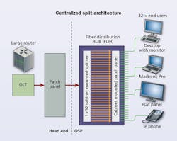
Centralized Split Architecture. In this architecture, service providers deploy a fiber distribution hub (FDH), also called a PON splitter cabinet, in a central location in a neighborhood. A few PON feeder fibers are deployed from the central office/headend to the FDH cabinet, where each feeder fiber’s optical signal is split according to the desired split ratio in the cabinet. Larger count distribution fibers are spliced in or near the cabinet, providing one or sometimes two distribution fibers for each home in a neighborhood.
The FDH cabinet becomes the one central location in the network where the splitters for that area are housed. A Centralized Split Architecture is often used to optimize cash flow during the network build-when the expected subscriber take rate is unknown, as the architecture’s higher splitter output port efficiency allows providers to minimize the purchase of splitters initially in the network, then add them as the take rate increases. Centralized split also reduces points of failure in the network, simplifying network troubleshooting and fault location that directly translate into labor savings.
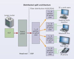
Distributed Split Architecture. This architecture is an older approach that can be used when subscriber take rates are expected to be high, for example, in a municipality build where the town or city already has an existing-and successful-relationship with the customer base. In this architecture, splitters are placed deeper into the network in a cascade or tree-type design to achieve the desired split ratio. Virtually any split combination can be achieved by using multiple splitters, for example a 1:4 splitter can feed four 1:8 splitters. Because the splitters ae not centralized, the need for a FDH cabinet is reduced or removed. The Distributed Split Architecture uses as few splices as possible, reducing reliance on highly skilled technicians.
The key component in this type of network is a terminal with an optical splitter inside. These terminals are fed with a single fiber and the optical power is split into the desired split ratio. The input is located in the central port of the terminal and the outputs are found on the outer ring of connectors. The only splice is at the very beginning, typically located in a splice case.
The disadvantage of this design is it can increase network complexity, oftentimes without the benefit of reducing fiber count. Locating faults can be more difficult because of the wide array of splitters, and network reliability might be impacted by an increase in optical components.
Providers need to weigh each of these architectures thoroughly to understand which will meet the overall requirements of their build, including capex costs, labor costs, geography and expected take rates.
Plug-and-play technology
Regardless of which architecture is selected, there’s an emerging trend that is simplifying fiber rollouts significantly: plug-and-play technology. While this term means different things throughout the industry, what it means here is the use of preterminated terminals and low-loss connectors in the field instead of fusion or mechanical splices, reducing the need for highly skilled labor and speeding up the installation processes.
In a traditional PON build, one or two splices are performed for every customer drop-a costly practice. By providing a preterminated terminal with low-loss connectors in them, a lower-level technician can be sent to inspect, clean and install one end of a double-ended patch cord into the terminal, and then push or pull a connector toward the home. Advances in pushable fiber and microduct have solved previous slack storage problems. The cable signature for these new fibers is so small that 50 feet of slack in a small flower pot or pedestal is easy to accommodate.
Plug-and-play technology also helps speed up the installation process. Microduct can be installed with a variety of methods, depending on the environmental conditions: microtrenching, directional boring or vibratory plowing. Once the duct is in place, it is simple to pull or push a terminated cable into the duct.
Putting it all together
One of the biggest concerns for most projects is total cost of ownership, or the combination of both capital expenditures and operational expenditures needed to see a project through to completion. While in some deployments, a Centralized Split Architecture may be the best fit, other scenarios call for a Distributed Split Architecture. In both scenarios, having a plug-and-play fiber solution reduces the need for a highly trained fiber splicer at each customer turn up, simplifying design and installation, and reducing the project’s overall cost.
Because every fiber deployment has unique circumstances, what providers need the most is the flexibility to choose solutions that match the job at hand with an eye on turning up subscribers and capturing revenue as quickly as possible.
Tom Warren is an application engineer with Clearfield (www.clearfieldconnection.com).

