Protocol and hardware testing for 2.5GBase-T and 5GBase-T
By Mike Klempa, University of New Hampshire InterOperability Laboratory
The University of New Hampshire InterOperability Laboratory (UNH-IOL) has been testing Base-T Ethernet since 1988. Ethernet speed increases have traditionally been a factor of 10, starting at 10Base-T and going to 10GBase-T (10-Mbit, 100-Mbit, 1-Gbit, 10-Gbit), but technologies based on the IEEE 802.11ac standard for wireless access are creating the need for a much more tailored approach to Ethernet standards development. A perfect example of this is the IEEE 802.3bz specification for 2.5GBase-T and 5GBase-T Ethernet. Modern access points created a need for greater than 1-Gbit/sec Ethernet connectivity over structured twisted-pair wiring, while maintaining a lower power and cost profile than was available using 10GBase-T. This new technology enables the existing and growing interconnect solutions for enterprise wireless access points to serve over structured Category 5e or better twisted pair. The ability to use existing cable combined with the lower power consumption makes it an attractive technology for access communications. This next generation of Base-T also shows a clear upgrade path as future access points (AP) and servers will need higher-speed access like 10, 25, or 40GBase-T, which all require an upgrade to the cabling infrastructure.
The 2.5/5GBase-T technology preserves the IEEE 802.3/Ethernet frame format utilizing IEEE 802.3 MAC (media access control), keeping the minimum and maximum frame size of the current IEEE 802.3 standard, supporting Clause 28 autonegotiation, optionally supporting Clause 78 Energy Efficient Ethernet, and PoE (covered in Clause 33). This also includes amendments made by IEEE 802.3bt DTE Power via MDI over 4-Pair Task Force. To ensure that a product is conformant to all of these requirements and testing basic interoperability, it must be tested over all layers, from the PMD (physical medium dependent) up to the MAC and even higher.
An area of particular interest to the cabling community is how the technology reaches speeds greater than 1 Gbit/sec, while continuing to use existing Category 5e installations. The usable bandwidth over these installations is 350 MHz. The clock rate of 2.5GBase-T is 200 MHz, translating to 625 Mbits/sec on each pair after the 64B/65B encoding and PAM 16 modulation. Similarly, the clock rate of 5GBase-T is 400 MHz, resulting in 1250 Mbits/sec per lane with the same encoding and modulation. Because of the limitation in bandwidth for Category 5e for 5GBase-T operation, the PSD (power spectral density) mask is shaped differently for 2.5GBase-T and 5GBase-T. It allows for more power at lower frequencies for 5GBase-T to overcompensate for the lack of bandwidth.
The 2.5GBase-T mask is lower to reduce the possible effects of crosstalk on a 5GBase-T signal on the same installation. The encoding increases transition density by mapping the possible 264 possibilities of bit streams to the more signal-integrity-favorable sequences of the 265 bit streams. While you lose that 1/65 headroom, the signal-integrity advantages are worth it. The pulse amplitude modulation (PAM) of 16 levels increases the baud rate by 4 at the same transmission speed. The symbol also goes through a Tomlinson-Harashima precoder (THP), which maps the PAM16 input in each dimension of the 4D symbol into a quasi-continuous discrete-time value. Basically, it turns this signal into a blob that is unintelligible to the human eye, but the blob is impervious to noise/interference because it pretty much was turned into noise. The receiver knows how to undo the THP, resulting in a clean bit stream. The benefit of this is it maximizes channel capacity without needing to increase the power to get a good enough signal-to-noise ratio (SNR), or needing the receiver to gain knowledge of the interference state through some sort of training.
Conformance testing
The protocols and signaling that a device needs to adhere to for the best chance of interoperability are broad and encompass many layers of the Ethernet stack. However the 2.5/5GBase-T technology is built on the robust foundation of prior Ethernet generations and even at its infancy showed robust interoperability.
First it leverages autonegotiation to determine optimal link speed. In this handshaking sequence devices must send a series of link pulses to advertise their capabilities. Autonegotiation is the Ethernet protocol that when correctly implemented, allows for a “plug and play” scenario between any two similarly capable devices. To ensure higher-level protocols are correctly supported, a device also needs to adhere to specific MAC and Flow Control protocol conformance specifications.
The electrical conformance testing follows the PMD requirements in IEEE 802.3bz. This testing exercises a device’s transceiver to make sure the quality of the transceiver does not prohibit operation and interoperability in any way. To do so, a variety of test and measurement equipment is required. Specific test patterns, or test modes, are specified to perform these measurements, and are defined to stress the transmitter in different ways. For example, long segments of one level to another are tested to measure rise/fall time and droop versus a sinusoidal clock rate pattern to stress jitter.
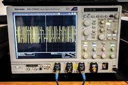
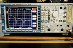
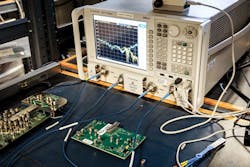
A real-time scope is required to measure the clock frequency, jitter and maximum output droop of a device. Clock frequency and jitter are measured to check the transmit signal against the ideal clock rate and transition time. A spectrum analyzer is required to measure the power spectral density, power level and nonlinear distortion of a transmitter. These are specified to limit the transmitted power from a port, which potentially limits the noise induced on the system as well as adheres to a desired power budget. A vector network analyzer is required to measure return loss. This shows the impedance match across the required operating frequency range. Any mismatch in impedance for a connection can cause reflections, which can increase the negative effects of crosstalk on a transceiver.
If a device is meant to support Energy Efficient Ethernet or Power over Ethernet, the extra circuitry and logic that is required also needs to be tested. Some of these added features can have negative effects on the electrical performance and state machines of the device, so they need to be checked thoroughly.
In addition to testing a device’s transmitter functionality, its ability to recover a worst-case signal is also tested. A compliant 2.5GBase-T or 5GBase-T transmitter, acting as the test station, sends packets to the device under test over 100 meters of 6-around-1 bundled Cat 5e cabling, testing the device under test’s receiver. The cable plant must meet the TIA TR-42.7/TSB-5021 requirements to be a valid test. This represents the worst-case signal that should still support a 2.5GBase-T or 5GBase-T link. It is assumed that if a link can be established under these worst-case conditions, it can establish a link with any other conformant device.
Cable testing
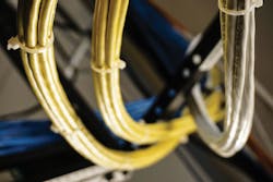
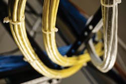
All the device requirements are built on the physical realities of the underlying cable plant. Due to the physical dimensions of Category cabling a common “worst case” assumption can be made about Category 5e. Crosstalk from outside the system under test, known as alien crosstalk, is at its maximum when there is no distance between the noise source and victim channel. Due to the dimensions of typical unshielded twisted-pair cabling, six cables wrapped tightly around another cable is the worst thing one can do for signal integrity. This also happens to be the desired way to run cabling for installers, who are looking to create neat and manageable cabling installations. (The best installations for this look like a jungle, but good luck troubleshooting that.) The six outside cables are bundled around a seventh cable, known as the “victim” cable. This cable is the most susceptible to, and affected by, the signal propagation down one of the outside lanes coupled into the middle cable or another outside cable, referred to as alien noise. These far end effects can negatively affect a link’s SNR, which could lower to a point where a link cannot be established due to the complex transmitting and encoding schemes used to squeeze 5 Gbits/sec out of a 400-MHz clock.
These assumptions and requirements were carefully vetted during the standardization process, and existing cable deployments were tested to ensure the compatibility with these new technologies. A typical cable test would involve handheld cable testing devices and a few relatively straightforward measurements. These measurements are similar to what was probably performed to qualify the installation in the first place, with a few more complex checks to ensure variables like alien crosstalk are not an issue. Insertion loss, or the loss through the channel, is an important measurement that usually dominates the reach capabilities of cabling. Return loss, as described above, is also measured on cabling to ensure a proper match broadband. Near end and far end crosstalk (NEXT, FEXT) limits ensure there is no egregious coupling in both the cabling and at the RJ45 connector. Propagation delay is typically known due to the physical properties of the materials that make up the cable, however excess delay can be an issue in regards to propagation delay skew, in which either the materials or twist ratio between pairs of cabling are not consistent, creating issues with latency. For a system designed to handle skew, as long as the skew is under the limit, there shouldn’t be a noticeable difference in the amount when measuring a bit error rate. Crosstalk and losses such as return loss and insertion loss would have a greater effect on the performance of the system in regards to cabling. Another cable quality benchmark test is the attenuation to crosstalk ratio (ACR), which makes sure the near end effects of crosstalk are less than the transmitted signal after attenuation. Devices won’t be able to operate at the faster speeds like 10GBase-T and 5GBase-T if the SNR is too low because of poor ACR.
The new Base-T speeds are a contemporary solution to an old problem that has come to light with the increases in AP throughput. It is important to thoroughly test both the protocol and physical layers of this nuanced technology, because devices likely need to interoperate with legacy Base-T devices ranging from 10Base-T to 10GBase-T, which could expose potential issues in implementation. Understanding the standard, the equipment needed, and the actual testing can sometimes seem as complex as the very development of a Base-T device, however proper conformance testing usually leads to faster deployment and fewer issues seen in the field in the grand scheme of things. Many users will benefit from the 2.5GBase-T/5GBase-T noticeable gain in bandwidth, while at the same time realizing cost savings from reuse of the Category 5e already in deployment.
Michael Klempa is the Ethernet and Storage technical manager of the SAS, SATA, PCIe, Fast, Gigabit and 10-Gig Ethernet Consortia at the University of New Hampshire InterOperability Laboratory (UNH-IOL). He began working at the UNH-IOL in 2009 as an undergraduate student at the University of New Hampshire. He obtained his bachelors of science degree in electrical engineering in 2013 and is currently pursuing a masters degree in electrical engineering. Michael’s primary roles at the UNH-IOL are to oversee the student employees in the SAS, SATA, PCIe, Fast, Gigabit, and 10-Gig Consortia, and conduct research-and-development in the technologies. He is frequently invited to speak at industry seminars and conferences, and has authored numerous technical articles.
